
Parts fitting individually on a printer do not automatically form a good assembly. Decide where seams may appear, how pieces align and the order of assembly before production. This guide concerns a non-load-bearing display model.
Download the English project worksheet. Open it as UTF-8 CSV, replace the guide context with your project inputs and record observations separately from acceptance decisions. Blank cells do not indicate a passed check.
Choose loose parts or an assembled delivery
Identify who joins the parts, additional components and whether the object must reopen. That determines access for tools, screws, clips or adhesive faces. Treat Print & Assembly as a delivery agreement, with extra components and assembly explicitly quoted. Use clearance and tolerance guidance for adjoining features.
Record total dimensions, function and visible sides. Ask what production envelope actually applies rather than inferring it from a printer name. If the limit is unknown, the split remains provisional.
Plan seams around visible geometry
Place seams around the visible faces
Mark front, rear, top and underside. Prefer a deliberate transition, edge or less visible face where appropriate. A cut through a plain front makes alignment and finishing more demanding. State whether each seam may remain visible, needs finishing or requires moving the cut.
The annotated original diagram shows a fictional 600 mm decorative object in three parts. It is a planning illustration, not evidence of available production or assembly capacity.
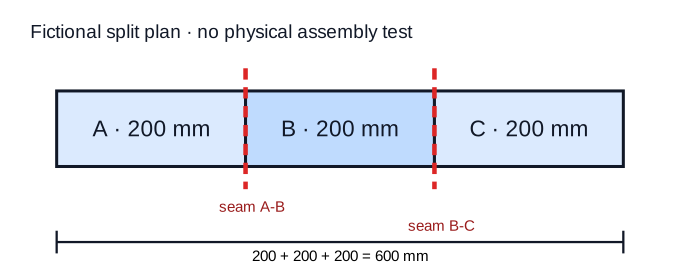
| Part | Planned length | Joining faces | Visible-seam rule | Alignment |
|---|---|---|---|---|
| A | 200 mm | Right | Keep seam off front | Two marks |
| B | 200 mm | Left and right | Follow a form transition | Plane and mark |
| C | 200 mm | Left | Rear seam acceptable | Two marks |
The sum of 200 + 200 + 200 verifies only the planned 600 mm length. Add agreed clearances or material allowances after choosing the connection. For scaled objects, first inspect scale and small details. For buildings, coordinate cuts with the architectural-model part and base plan.
Alignment is not connection strength
A pin, mating edge, plane or mark helps position parts. It does not prove that the joint carries its intended load. Adhesive choice depends on actual materials, surfaces and use; mechanical connections need their own assessment. For a permanent PLA joint, plan a representative adhesive trial. Stop when material, loading or connection remains unknown.
Walk through the assembly before making the parts
Write the sequence: place A on a flat surface; dry-fit B and compare marks; dry-fit C; measure the total; inspect seams; only then apply the agreed connection. Check that hands and tools can reach every joint. The plan fails if the last part blocks an earlier connection, assembly damages the front or the final dimension cannot be measured.
Check dry fit before final assembly
Use the same part letters in filenames, numbered sketch and instructions. Approval requires dry-fitting in the intended order, total dimensions within the agreed limit and every visible seam accepted. Without physical dry-fitting, this remains a design decision rather than an observed result.
Commission the missing step
If cuts, alignment or connections still need adding digitally, send the source and numbered sketch for 3D modelling. Specify permitted seams and access. “Print it in three pieces” leaves those design choices unresolved.
If the separate models are already checked, request loose pieces or a completed object through Print & Assembly. Confirm the real production envelope and joint before fixing the split. The fictional 600 mm example is not a capacity promise.