Quality and process

A 3D print starts with the job it needs to do.

Fit, strength, suitability for the environment and a considered finish depend on decisions made before printing. Here you can see how we assess those decisions at OmniTechs, with real workshop photographs and the visible results of a three-version print trial.

Will my file simply be sent to a printer?

Before printing we assess wall thickness, overhangs, tolerances and the intended visible face. Orientation and settings depend on the function. Where dimensions, fit or loads introduce a critical risk, a test piece may be needed before accepting a version as the finished product.

Workshop case · three iterations

Three versions of one FDM part: improvements and remaining limits

This part initially showed sagging in a horizontal hole and an uneven surface. Layer height, speeds, cooling and the top surface were adjusted across three versions. The photographs show visible changes and remaining FDM marks. They do not establish measured fit, load capacity or final customer acceptance.

Not every part needs three prints. Simple or previously validated geometries can go straight to production. Layered FDM surfaces also remain different from polished glass or injection-moulded finishes.

A horizontal hole, an unsupported bridge or a critical top face can justify staged trials. This case follows real iterations of an anonymised black PLA+ part from our Groningen workshop.

Part and environment

A black PLA+ component for a folding stand

The customer supplied a model of a long U-shaped component with a horizontal hole near its rounded end.

During intake, the customer described indoor use, no regular direct sunlight and a mounted device that does not become noticeably warm.

Black SUNLU PLA+ was a defensible starting point within that reported environment. It is not a general material guarantee; prolonged sunlight, heat, moisture or different loading require reassessment.

Recorded trial settings

Settings used for this particular geometry

These starting and test values were adjusted for this job with a 0.4 mm nozzle. They are not universal recipes or guarantees for other models.

Filament and colour
Black SUNLU PLA+
Selected for the reported moderate indoor environment without a heat source
Nozzle diameter
0.4 mm
Balance between detail and production speed
Layer height
0.12 mm
Finer steps around the horizontal hole
Wall count
4 walls
More material around the hole and a stiffer wall structure as a starting point
Solid top layers
4–5 top layers
Cover the infill without sagging lines
Top surface speed
Approximately 30–40 mm/s
Controlled deposition for a more even surface
Overhang speed
Approximately 20–30 mm/s
Limit curling at angled edges
Bridge speed
Approximately 20–25 mm/s
Control the unsupported span above the hole
Ironing trial
20 mm/s, 12% flow, 0.10 mm spacing
Tune the top surface rather than treating ironing as an on/off setting
Version 1 · initial trial

Identify the risks in the first output

Sagging above the horizontal hole and rough outer contours

Observations and analysis

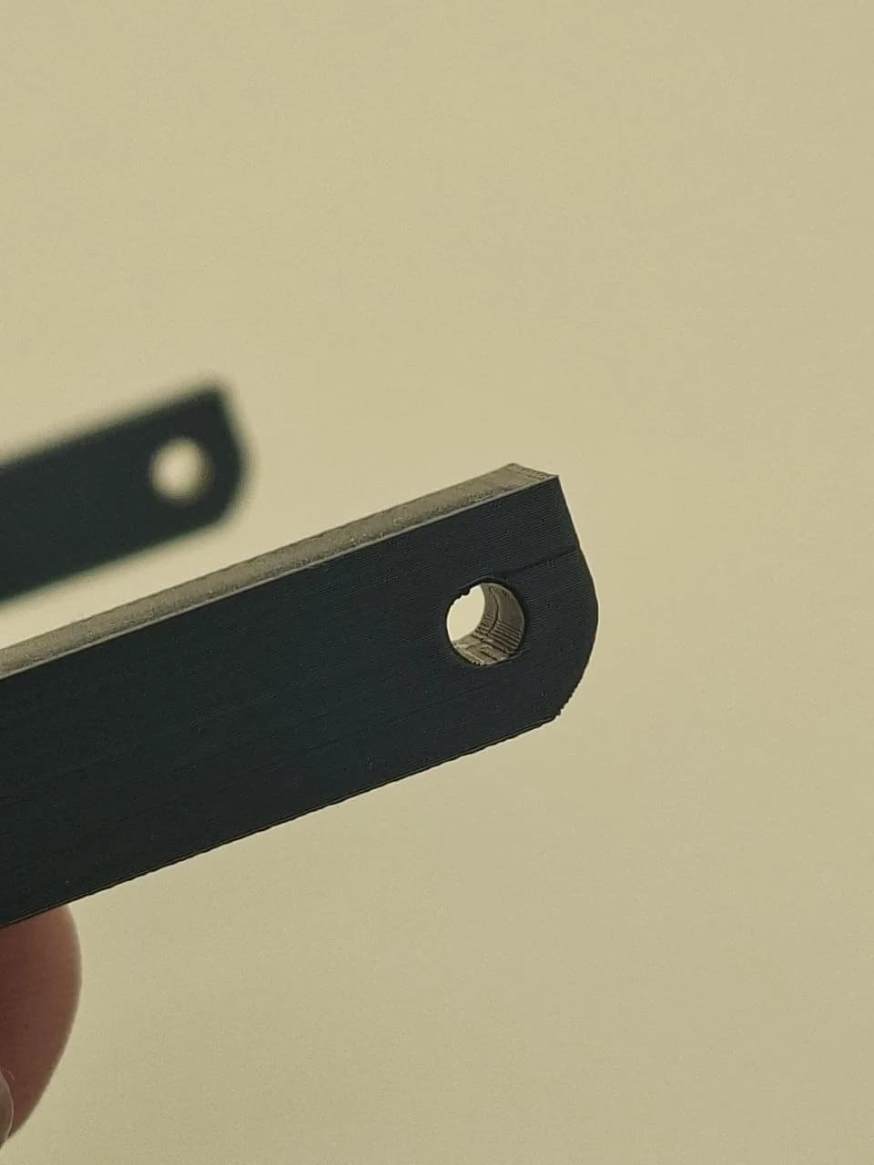
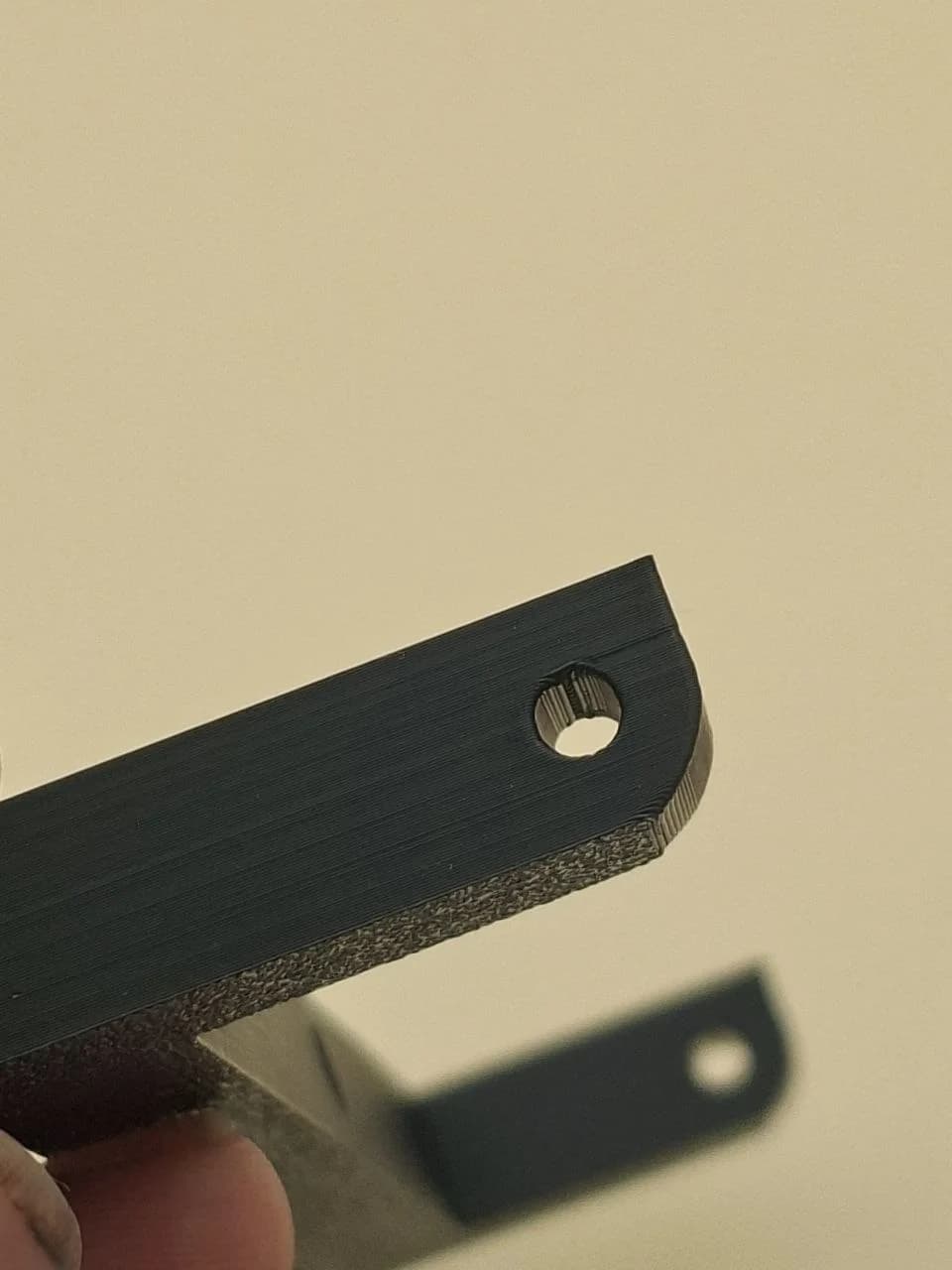
The initial trial with standard settings showed sagging at the transition between the overhang and bridge above the horizontal fixing hole.

Without support, the upper circular layers had to span open space. Outer edges and the surface also showed uneven and ragged areas.

Even if the part might have been usable, the sagging hole and uneven finish were reasons to investigate before proceeding.

Actions taken

  • Reduce layer height to improve the stepped approximation of the circular hole.
  • Assess bridge and overhang speeds to address unsupported sagging.
  • Prepare cooling and bed adhesion for the finer layer structure.
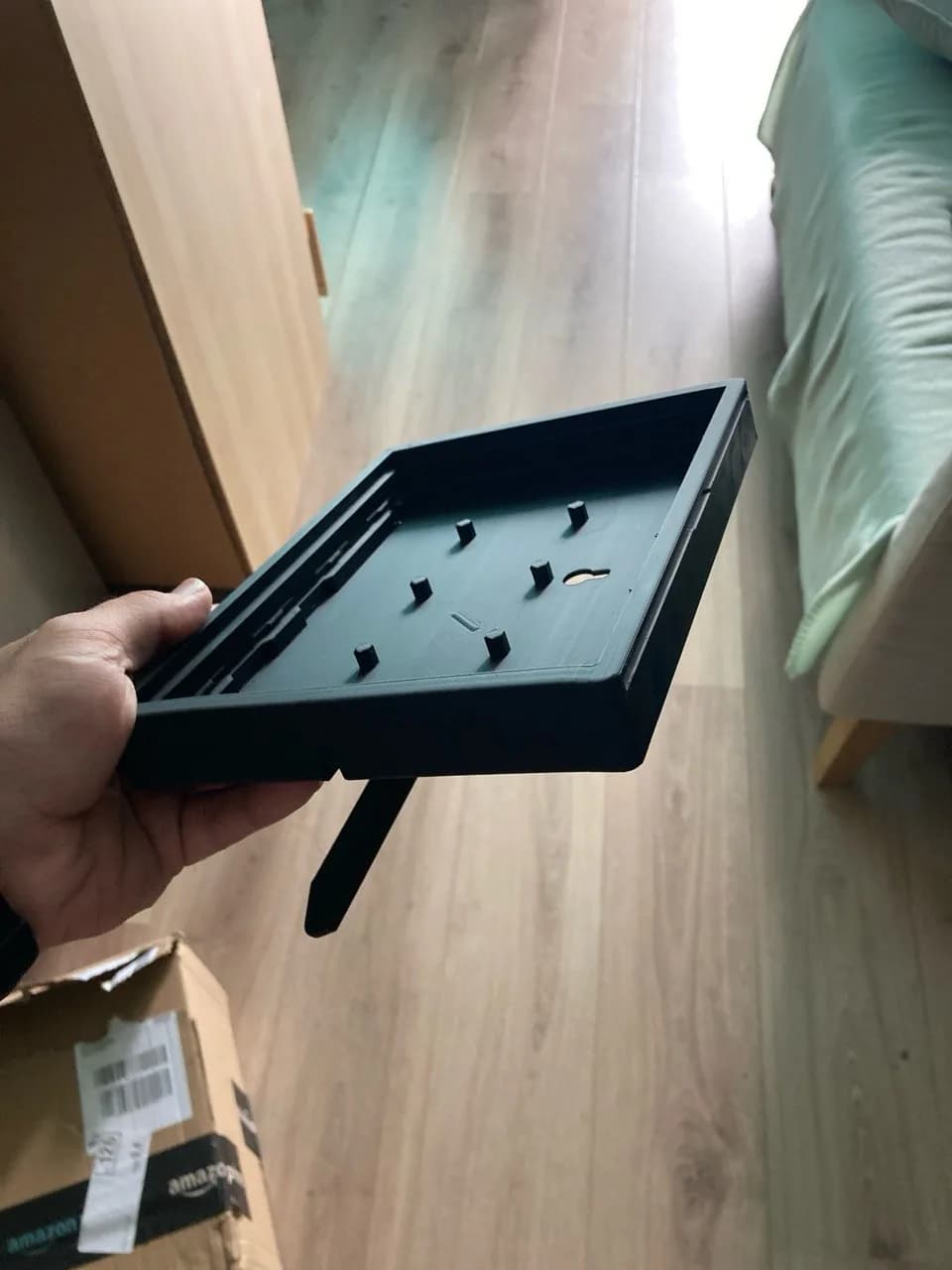
Angled view of the first black PLA+ trial with a rough horizontal hole and uneven edges.
Version 1: distortion and rough transitions around the horizontal fixing hole.
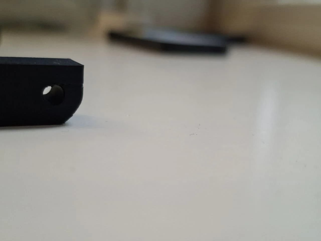
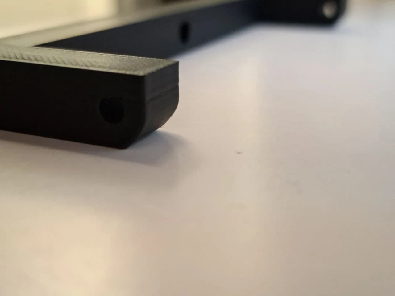
Side view of version 1 showing sagging bridge material at the top of the hole.
Version 1 detail: unsupported material sagged at the roof of the horizontal hole.
Version 2 · adjustment and analysis

Finer layers, corner lift and several possible causes

A rounder-looking hole with remaining bridge strands and a line at hole height

Observations and analysis

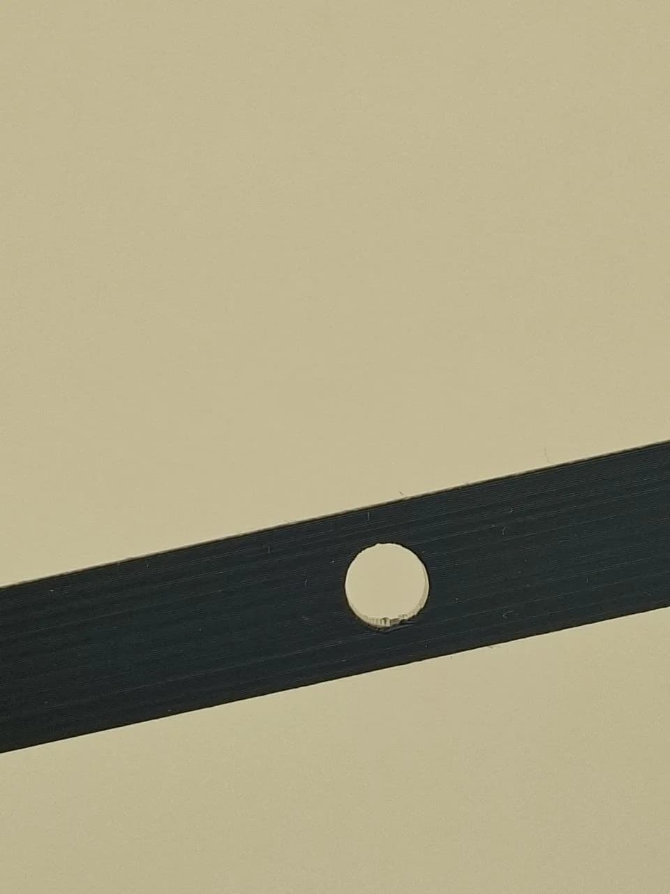
Version 2 used 0.12 mm layers and showed a rounder-looking hole. Several settings changed, so the photographs do not isolate the contribution of layer height alone.

Inspection also revealed slight corner lift and horizontal lines near the bottom and top of the hole. Bed adhesion, cooling and thermal shrinkage needed further attention.

Possible causes of the line included different layer times through the hole, flow transitions between walls and bridges, and local shrinkage at changes in cross-section. The photographs alone do not establish one proven cause.

Actions taken

  • Rebalance bed temperature, adhesion and cooling to limit corner lift.
  • Coordinate overhang speeds around 20–30 mm/s and bridge speeds around 20–25 mm/s with the wall settings.
  • Inspect the untreated diagonal top lines before calibrating ironing.
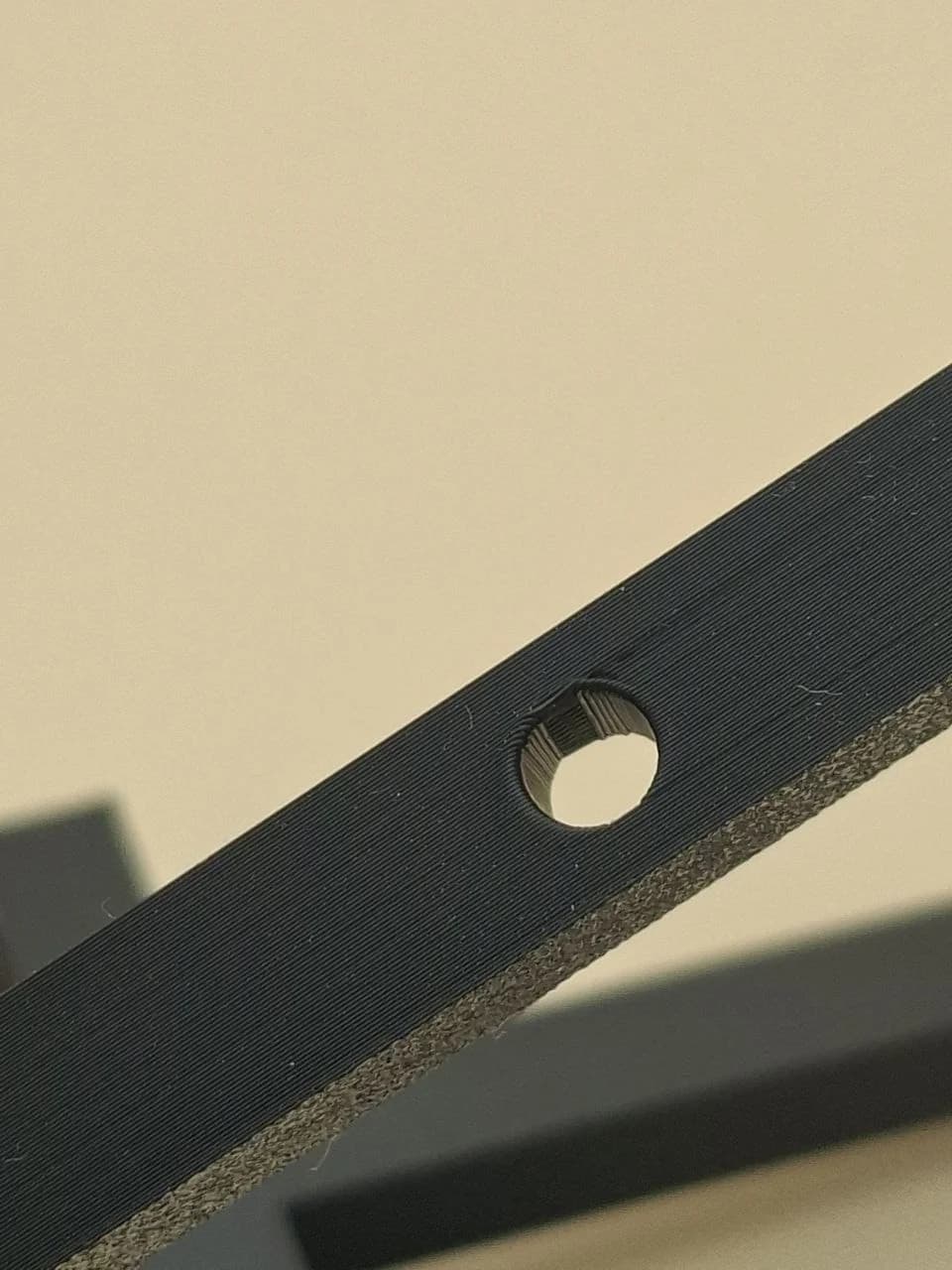
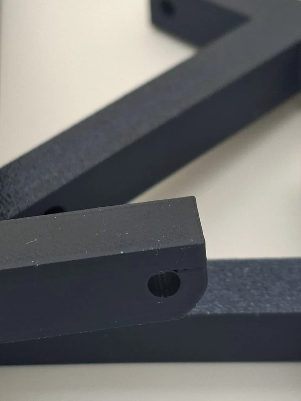
Version 2 hole at 0.12 mm layer height with remaining bridge strands.
Version 2: a rounder-looking hole, with remaining bridge strands. This is a visual comparison, not a dimensional or load test.
Version 2 side wall with a horizontal line at hole height and slight corner lift.
Layer time, cooling and flow were possible causes to investigate for the line and corner lift.
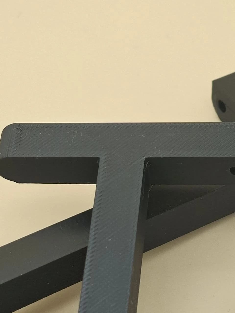
Untreated top surface of version 2 with visible diagonal extrusion lines.
Version 2 top detail before ironing calibration.
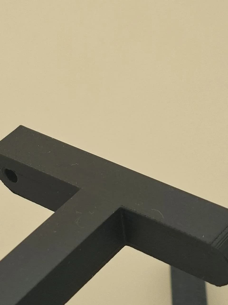
Top view of the black version 2 bracket showing the FDM extrusion pattern.
The photograph records surface texture, not mechanical strength.
Version 3 · further trial and inspection

A more even top surface and a less prominent seam

Ironing calibration and seam placement on the underside and inside

Observations and analysis

This version was recorded as an inspection candidate. The photographs are not evidence of customer acceptance or a formal dimensional tolerance.

Ironing was tested at 20 mm/s, 12% flow and 0.10 mm spacing. The surface became more even while retaining FDM texture. Enabling ironing alone can still leave ridges or too much or too little material.

Seam painting moved perimeter start and stop points towards the less visible underside and inside of the U shape. The seam remains physically present; close-ups show a local mark.

The hole looks rounder and the visible surface more even than earlier trials. Layer lines and local marks remain around and inside the hole, which is why inspection from several angles matters.

Actions taken

  • Test ironing at 20 mm/s, 12% flow and 0.10 mm spacing over 4–5 top layers.
  • Move the seam towards the underside and inside using seam painting.
  • Inspect the hole, flatness, edge finish and remaining marks from several angles.
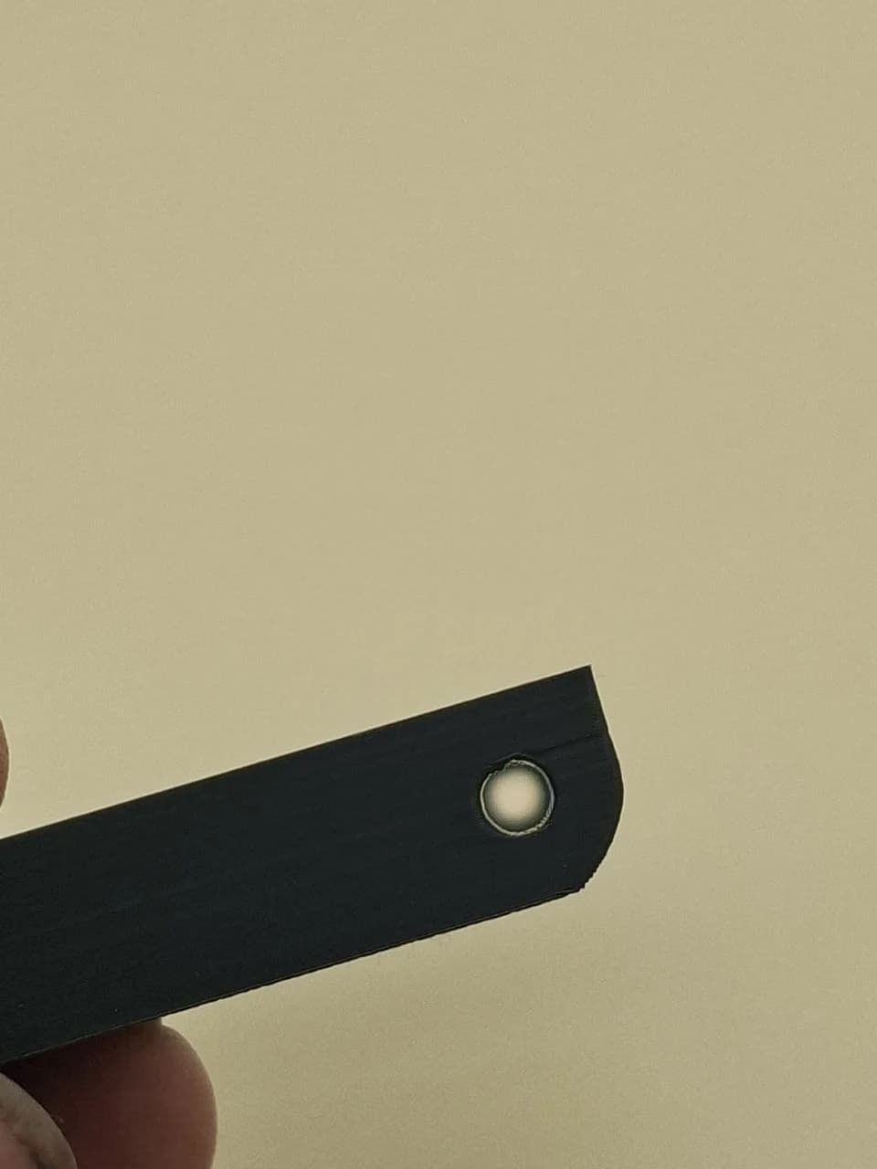
Front inspection of the version 3 horizontal hole and surrounding edge.
Version 3 front: clearer roundness, without a measured tolerance claim.
Angled inspection of version 3 showing the outer wall, layer lines and hole.
The outer wall looks more even; layer lines and marks in the hole remain visible.
Close-up of remaining bridge and seam marks inside the version 3 hole.
The hole has improved visually, but local bridge and seam marks remain.
Local seam mark on the underside of the version 3 horizontal hole.
The seam is relocated to the lower, less frontal side; it has not disappeared.
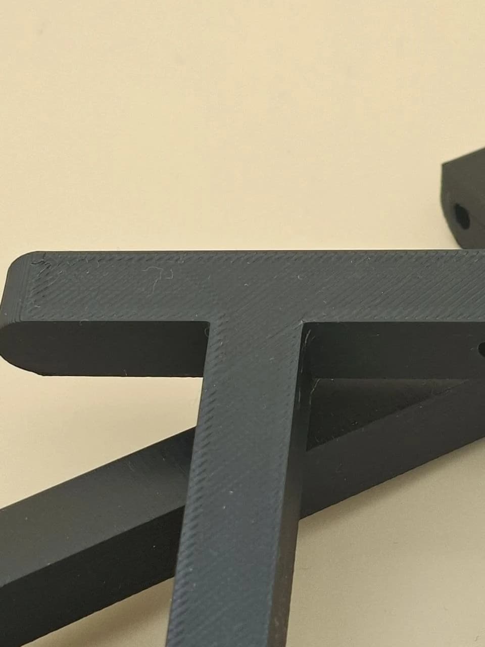
Ironed top surface of version 3 with a more even matte finish and remaining FDM texture.
The tested ironing settings make the top more even, while fine FDM lines remain.

Discuss the critical features in your file

Send the model, drawing or part and identify important fits, spans and visible faces. We assess whether a test piece or targeted slicer adjustment is appropriate.

Project status

Published customer review

Printed architectural designs

This assignment involved several architectural models. The public Trustpilot review describes the quality and delivery of that work.

Read the Trustpilot review

Inside the workshop

Where the work is assessed, printed and finished

Actual photographs from the Groningen workshop, rather than stock images or renders.

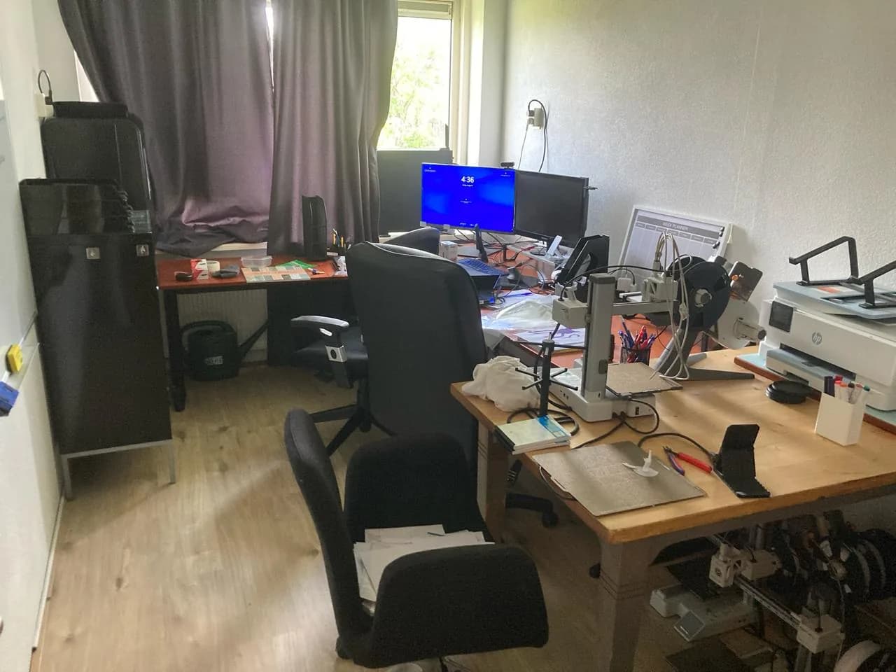
The OmniTechs workshop in Groningen with 3D printers, a workbench and monitors.
The workshop in Groningen: four printers, a workbench, and the monitor the slicer runs on.
Sina Esfahani in safety glasses and a glove during post-processing of 3D prints.
Post-processing is done by hand, with glasses and gloves — not by a machine that solves everything.
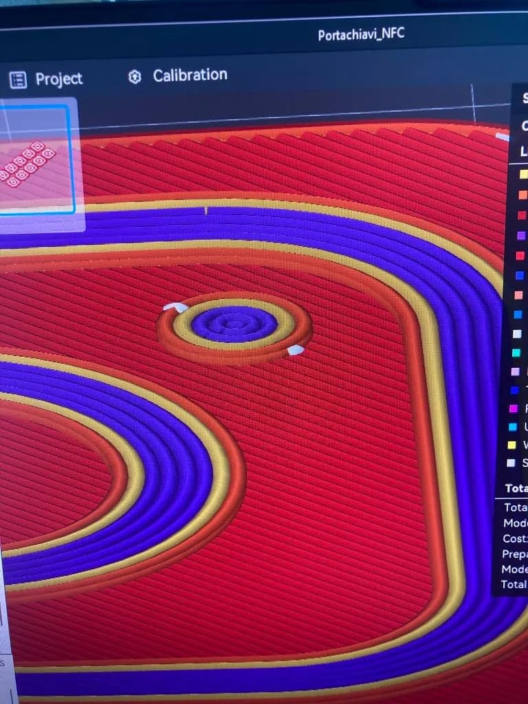
Slicer view of the layer structure of a keychain with a pocket for an NFC inlay.
Layer view in the slicer. The pocket the NFC inlay drops into is decided before anything prints.
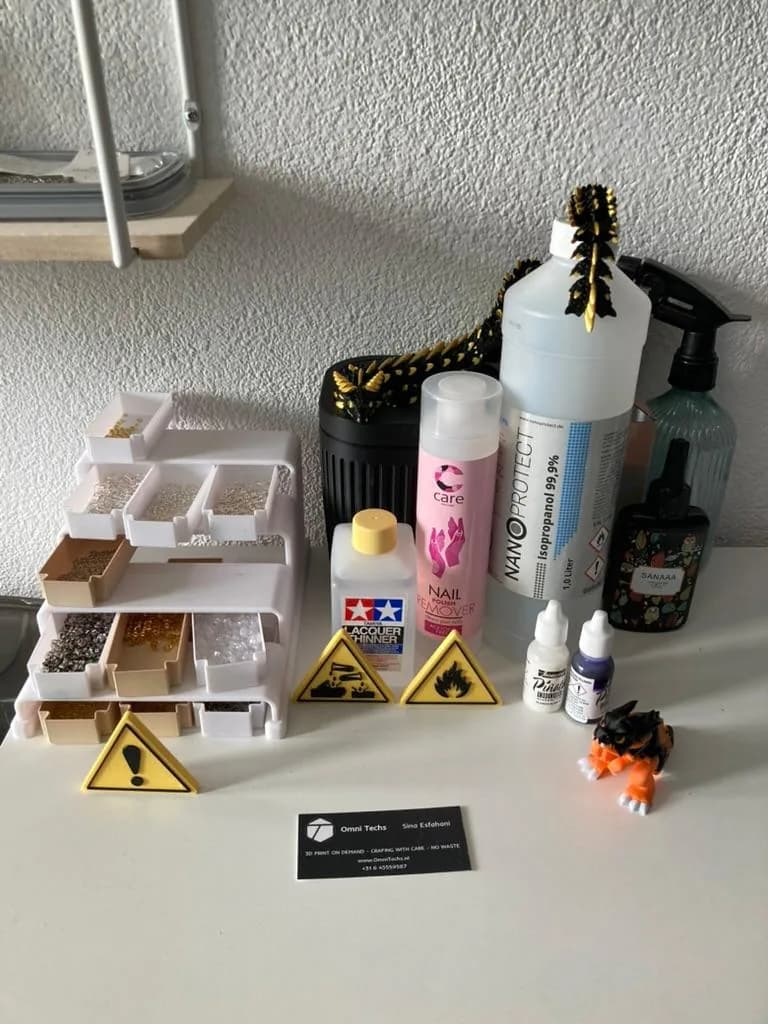
Finishing station with isopropanol, pigments, sorted hardware and hazard labels.
The finishing station: isopropanol, pigments, sorted inserts, and the hazard labels that go with them.
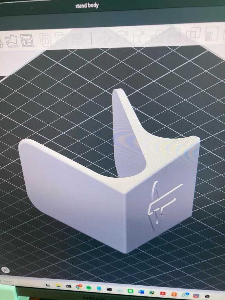
CAD model of a folding phone stand with an engraved logo.
The model first: a folding stand with the logo cut into the side wall.
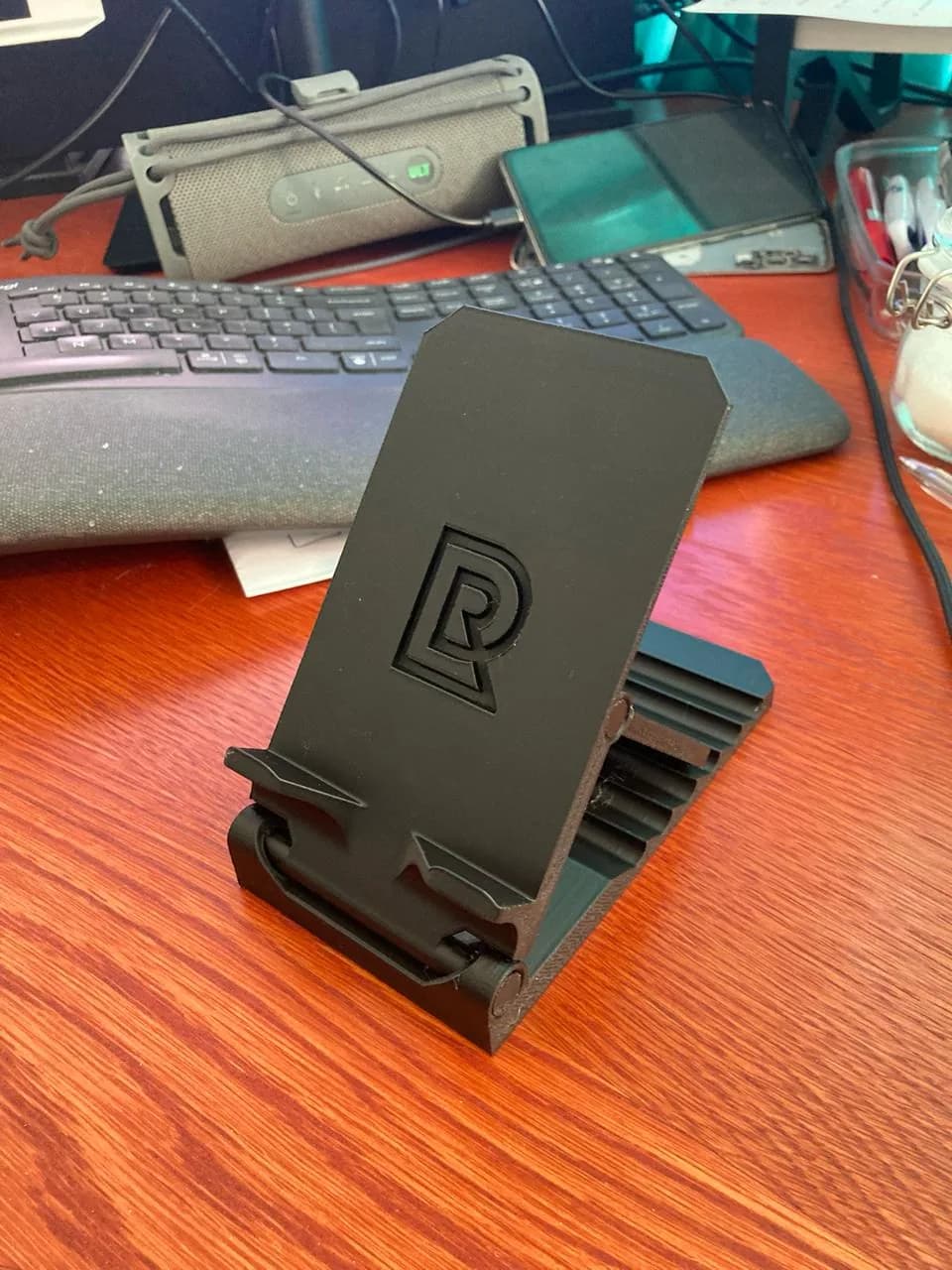
3D-printed phone stand in matte black with an engraved logo, on a desk.
Then the part. The same model, printed and folded shut on the desk.
3D-printed enclosure with cut-outs and clip joints, held in one hand.
A functional enclosure with clips and pass-throughs — not decoration, a part that has to fit.

Assess the function before selecting the settings

What must the part do, where is it loaded and what happens if it fails? Those questions matter for every request, including objects that do not look particularly technical.

The approach draws on a civil-engineering background, years of 3D design software experience and more than two years of practical FDM printing. This informs the assessment of geometry, load and failure direction. It does not make a print a certified structural calculation.

Professional recommendation

Sina demonstrated an incredible aptitude for programming languages such as TCL and MATLAB, which he skillfully utilized to develop a civil engineering development tool.

Mostafa FarajianMentor and thesis supervisor during Sina's earthquake-engineering research (civil engineering)LinkedIn recommendation

Check the file against the intended product

STL or 3MF does not automatically mean production-ready. Wall thickness, small details, hole and joint clearance, overhangs, bridges and support placement all require review. Removing support can affect the most visible surface.

When we identify a clear risk, we discuss it before final production. A small model change, a different material or another orientation may be appropriate.

Strength depends on more than infill

A high infill percentage does not compensate for an unsuitable layer direction, thin walls or a load that pulls layers apart.

For functional parts we consider material, wall thickness and wall count, orientation, layer bonding and geometry together with the direction and type of load. Formal load testing or certification must be discussed separately.

Decide what a trial must demonstrate

For critical dimensions, a new joint or an unfamiliar fit, a test piece can isolate the risk before repeating a whole order. The first output is assessed against the agreed requirements.

A finished part must meet the agreed function, fit and appearance requirements. Simple or previously established models do not need an unnecessary three-print sequence.

Check appearance separately from function

Seams, support marks and uneven top surfaces require deliberate choices. We identify the visible face, seam location and support areas where appearance matters.

A technically usable print can still have a poor finish. Function and appearance therefore have separate checks; the FDM process still leaves layer texture.

Recognise common print risks before production

Material choice, geometry, orientation and settings influence the result. We consider these issues together rather than assuming that a successful print cycle proves the part is suitable:

  • Warping: lifted corners can relate to bed adhesion, geometry, cooling and material.
  • Layer-direction weakness: a solid-looking part may still break along layer boundaries.
  • Poor fit: printed holes can differ from the file, so critical dimensions and clearances need agreement.
  • Support marks: support placement should account for the important visible surface.
  • Weak fixing points: local stress around screws is not solved by infill percentage alone.
  • Environmental mismatch: heat, moisture or sunlight may change a part that initially looks satisfactory.
  • Unprintable detail: thin walls, isolated details and overhangs require review before production.

Choose another process when it fits the job better

Some applications need another material, manufacturing process or specialist producer. A print is not automatically validated for medical, load-bearing or other safety-critical use. Explain required certification or testing before we assess the request.

Connect the physical object to its digital purpose

OmniTechs also develops digital products. A physical object can be combined with NFC, QR, a digital page or automation where the project needs it. Agree those functions and responsibilities alongside the printed parts.

Direct contact with the maker in Groningen

Regular plastic prints are produced in our Groningen workshop. You discuss the request directly with the person assessing the file, choosing the settings and inspecting the result.

Questions about quality and process

Is every part printed several times?

No. Simple or previously proven parts can proceed directly after file assessment. Trials are used where critical dimensions, a new connection or an unfamiliar risk justify them.

Is 100% infill always strongest?

No. Material, walls, orientation, layer bonding and geometry also matter. A well-oriented part with appropriate walls can perform better in the relevant direction than a poorly designed solid print.

Can you assess an existing file?

Yes. We review walls, overhangs, supports, orientation and dimensions. Functional parts also need information about use and loading.

What accuracy can you guarantee?

There is no universal tolerance for every shape, size, material and orientation. Identify critical dimensions so we can agree whether a test piece or measurement is required.

Do you make safety-critical parts?

A print is not automatically certified for medical, structural, electrical or other critical uses. State formal certification or validated loading requirements first; a specialist producer may be more appropriate.

Can a printed part be used outdoors?

Suitability depends on material, duration, temperature, sunlight, moisture and load. Describe the environment before a material or approach is selected.

Have your file, part or idea assessed

Describe the function, what you already have and your required date. We clarify missing requirements and risks before quoting.