
Orientation affects more than print time. It changes layer direction, support contact, seam placement, mating surfaces and the relationship between loading and layer interfaces. Compare at least two options on the same model with the same requirements.
Changing orientation and post-processing the finish are separate choices. Moving a visible face may place supports on a mating face instead. The real horizontal-hole case study shows visual iterations, not a load test. Discuss fit and clearance separately from appearance.
Download the English project worksheet. Open it as UTF-8 CSV, replace the guide context with your project inputs and record observations separately from acceptance decisions. Blank cells do not indicate a passed check.
Draw the function before choosing a build direction
Mark the main visible face, contact surfaces, mounting and arrows for pushing, pulling or bending. Without those priorities a producer can optimise only from geometry. The example is a fictional non-critical wall-hook shape; no physical trial, load capacity or safety performance is established.
Define the planned prototype criteria. For a fine display model, use the visible-detail assessment to rank surfaces.
Compare two orientations explicitly
Draw A lying down and B rotated 90 degrees. Show build direction, visible side, part-relative load arrow, possible seam and support zones in each. The original orientation diagram, illustrates this comparison using one shared L-profile.
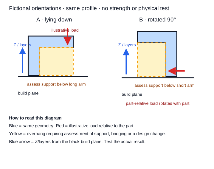
| Point | A: lying down | B: standing |
|---|---|---|
| Geometry | L-profile | Same profile rotated 90° |
| Build contact | End of short leg | End of long arm |
| Load arrow | Downward at arm end | Same part-relative arrow rotated with the part |
| Possible seam | Rear edge | Long side edge |
| Support question | Under long overhang | Under short overhang |
This synthetic comparison has no universal winner. Actual consequences depend on geometry, material, settings and finishing.
Make visible marks an explicit criterion
State where first-layer texture, seams and support contact are acceptable, and inspect at the agreed distance and light. A relocated seam has not disappeared. If both options affect an important face, consider changing geometry, splitting the model or making a representative sample.
Separate direction from load-capacity evidence
Build direction, raster and layer interfaces are relevant variables, but identifying them does not establish an allowable load. Structural or safety use needs appropriate material evidence, design assessment, production controls and physical testing. An orientation sketch is not technical validation. For how orientation combines with walls, infill and geometry under load, see how strong 3D-printed parts are and what to change. Stop if consequential loading is undefined or failure can cause injury or damage.
Choose a bounded trial, not an assumed final setting
Assign a test to each priority
Record visible face, load arrow, mating surfaces, two orientations, support and seam effects and uncertainties. Give each criterion an owner and a test method. At this stage, proceeding means selecting an option for a defined trial, not proving lifetime or capacity.
Give the producer priorities and comparison sketches
Send both sketches and the model to the 3D printing service, ranking appearance, fit and the described loading. Ask the producer to assess orientation and support against those priorities. If requirements conflict, discuss a limited sample or a different split. Record the trial's orientation so later revisions can be compared fairly.