
You have a part that has to hold, clamp or absorb something, and you want to know what to change so it does that reliably. The short answer: the strength of a 3D-printed part depends on what it has to withstand, how it was oriented in the printer, how its shape carries the load, and which material was printed under which conditions. An infill percentage on its own cannot tell you how much a part will carry.
This guide covers plastic parts made by FDM/FFF, the process in which a printer lays down molten filament in lines and layers. It helps you define the requirement first, then choose between more walls, more infill, a different print orientation, a design change or a different material, and finally judge what a test does and does not prove.
Already facing a specific problem? If the part bends too far, breaks at a screw hole, splits along the layer lines or slowly sags, go straight to the decision table under What should you change for your particular problem? and then read the explanation behind the row that matches.
Throughout the guide we use one illustrative example: an L-shaped bracket screwed to the side of a desk with two screws, carrying a light cable tray. The load acts downwards at the end of the arm. It is a low-risk part used to explain decisions. It is not a customer project and it has not been tested.
What does your part need to withstand?
"Strong enough" is not a property of a filament or a slicer setting. It is an agreement about an application. Before you change anything in the slicer, be clear about what the part is expected to do.
Four terms to keep apart
- Strength is how much stress a material or part can take before it fails or deforms permanently. UltiMaker defines material strength as the maximum stress before failure, expressed in MPa.
- Stiffness is how much something deforms under load. A stiff part bends very little, yet it can still break suddenly.
- Toughness is how much energy a material absorbs before it breaks. A tough part deforms visibly first; a brittle one breaks with little warning.
- Acceptable deflection is how far the part may move before it stops doing its job. A bracket that does not break but sags until the cable tray tilts has still failed.
Many problems with printed parts are really stiffness problems: nothing breaks, but the part moves too much. That usually calls for a different fix from a part that snaps.
A material property is not the behaviour of your part
A datasheet reports values measured on test specimens under standardised conditions. Your part has its own shape, holes, corners, walls, infill and orientation. NIST's report on standards for polymer additive manufacturing points out that the performance of a printed part is shaped by internal fusion joints, print direction, manufacturer, process and material supplier. A specimen value is a basis for comparison, not the load capacity of your bracket.
Watch the units, too. A kilogram is a unit of mass, not force. A 1 kg mass hanging still exerts roughly 9.81 newtons under gravity. If it is placed down, knocked or dropped, the force can briefly be much higher. "It has to hold 2 kg" only becomes usable once you say how those 2 kg arrive on the part.
Direction, duration, repetition and environment
Also record:
- Loading direction: does the force push, pull, bend or twist, and where does it act?
- Duration: a brief push is different from a weight that hangs there for months.
- Repetition: a snap fit opened hundreds of times is loaded differently from a bracket installed once.
- Environment: heat, sunlight, moisture and chemicals can make plastic weaker or more flexible.
A one-sentence requirement
Complete this sentence before changing any setting:
The part needs to [function], the force acts [where, in which direction, for how long and how often], acceptable movement is [how much, measured where], and the operating environment is [temperature, light, moisture, contact].
For the bracket: the part needs to carry a light cable tray, the force acts downwards at the end of the arm and is always present, the arm end may barely sag, and the environment is an office at room temperature out of direct sunlight. Every later decision can be checked against that sentence.
More walls or more infill: what should you change first?
An FDM part consists of an outer shell and an inner fill. Knowing which does what lets you make targeted changes.
What each element does
- Walls or perimeters are the outline paths of each layer. In the slicer you set how many wall lines are printed.
- Top and bottom layers are the solid layers that close the part above and below.
- Infill is the open internal structure inside the shell, set as a density percentage and a pattern.
- Geometric thickness is the thickness you model in CAD. It limits how much room there is for walls and infill.
Prusa's documentation on layers and perimeters states that a model's strength is mostly defined by the number of perimeters rather than the infill, and advises adding perimeters if you want a stronger print. Its infill documentation suggests 10–15% infill for most models and notes that you will rarely need more than 30%. Treat that as one slicer vendor's guidance for typical models, not a law for every part.
Why the shell often matters most in bending
When an arm like the bracket's bends, stress is highest at its outer surfaces: the top is stretched, the bottom compressed. In pure bending, stress near the middle is low. That is a basic principle of beam mechanics. So the outer walls carry a large share of a bending load, while the infill mainly keeps the shells apart and resists local compression. For a part that is mainly squeezed, or where a screw presses on one spot, infill can matter more.
Wall count, shell thickness and CAD thickness are three different numbers
The number of wall lines is not the wall thickness. The printed shell thickness depends on the number of lines and the extrusion line width, and line width does not automatically equal the nozzle diameter. Prusa gives the example of a 0.45 mm perimeter width with a 0.4 mm nozzle and explains that neighbouring perimeters overlap slightly. Two wall lines are therefore not exactly twice the line width.
Top and bottom layers work the same way: the number of layers multiplied by the layer height sets the thickness. Prusa notes that at a lower layer height you need more solid layers for the same thickness.
The CAD thickness limits everything. If a section of the bracket is thinner than twice the shell thickness you set, there is no room left for infill, and that zone ends up solid or filled with narrow gap-fill lines. Adding wall lines then changes little; the geometry is the constraint.
What to check in the slicer preview
Step through the sliced preview layer by layer where the part is loaded:
- How many wall lines actually surround the bracket's corner and its screw holes?
- Are thin sections completely filled, or are there small gaps between walls and infill?
- Do the top layers close properly over the infill?
- Is there enough material next to each hole, or does the hole wall run almost into the part's edge?
The preview shows what the printer will lay down. It does not show how strong that will be.
Why neither rule always holds
"More walls always wins" fails when the geometry is too thin, when the part is mainly loaded in compression, or when failure happens between layers. More outline paths within each layer do little against separation between layers.
"100% infill is always strongest" fails because a solid print is still made of lines and layers. Voids between lines do not automatically disappear, and the layer interfaces remain a weaker direction. Polymaker's PolyLite PETG datasheet reports values from specimens printed at 100% infill: strength in the Z direction, across the layers, is lower than in the X-Y direction, and elongation at break is markedly lower. Printing solid also costs more material and time, and a heavier part can add load of its own.
So change the parameter that matches the failure mode you are investigating, and change one thing at a time. If you are ordering the part, see what determines the cost of a printed part to understand how extra walls, infill and print time affect the price.
Why does print orientation matter?
Within a layer, neighbouring lines fuse side by side. Between layers, a new hot line has to bond to a layer that has already cooled. That interlayer bond is often the weaker direction in FDM. The NIST report describes printed parts as highly anisotropic, meaning their properties differ with direction, and summarises that for tensile loading the parts studied were generally stronger when the lines were aligned with the load.
Two ways to print the bracket
The illustrative sketch for this guide shows the same bracket in two orientations:
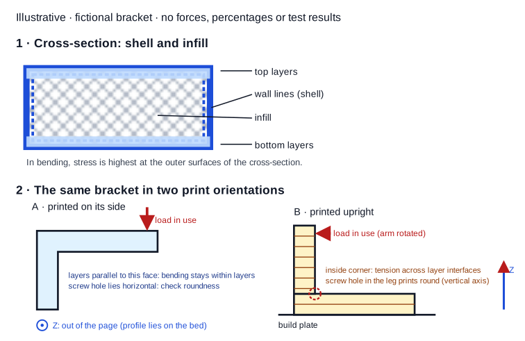
- Option A: on its side. The L-profile lies flat on the bed, so the layers run parallel to the bracket's side face. When the arm bends downwards in use, the tension along the top of the arm runs within the layers, along the printed lines.
- Option B: upright. The mounting leg lies flat on the bed and the arm grows upwards. In use, the arm then bends across the layer interfaces, and the tension at the inside corner pulls directly on the joins between layers.
For this load, A looks mechanically favourable. B has advantages of its own, though: the screw holes in the mounting leg print round with their axis vertical, while in option A they are horizontal and may show a bridged or distorted top edge. That can affect the fit and the material around the hole. Which option is better depends on where the part fails in your application: at the corner, or at the hole.
This is a trade-off, not a fixed winner. No percentage or load capacity can be attached to it without testing this specific part.
What to compare
Draw the load arrow on the part and ask, for each orientation: where is the highest tensile stress, and does it run along the printed lines or across the layer interfaces? Then look at the weakest feature that remains, such as a hole or a sharp corner. For the wider trade-off between visible faces, supports, mating surfaces and loading, see how to choose a print orientation around visible faces, fit and loading.
When does redesign help more than changing print settings?
If you keep adding walls and infill and the part stays too flexible or keeps breaking in the same place, you are probably trying to solve a design problem in the slicer. These are the design changes to investigate.
Cross-section and span
For a simple rectangular arm, beam theory says bending stiffness grows in proportion to width but with the cube of the thickness in the bending direction. Doubling that thickness makes the arm roughly eight times stiffer if the material stays the same. A printed part is not a uniform beam, so use this as a direction, not a calculated value.
- Aim: less deflection and lower stress.
- Trade-off: more material, print time and space; the thicker arm might clash with the cable tray.
- Still check: whether the corner or the holes now become the weakest point.
The lever arm matters in the same way: the further the load acts from the mounting leg, the larger the bending moment at the corner. A shorter arm, or a support point closer to the load, can achieve more than any setting.
Load path, corners and reinforcing ribs
Force travels from where it is applied to where the part is fixed. A sharp inside corner on that path creates a stress concentration: locally higher stress where a crack can easily start. UltiMaker's design guide recommends fillets or chamfers to reduce stress concentrations between layers, and internal ribs combined with sparse infill as an efficient way to reinforce a part.
- Fillet in the inside corner. Aim: spread the stress. Trade-off: may clash with a mating part that has to sit in the corner. Still check: that the fillet prints cleanly in the chosen orientation.
- Reinforcing rib between arm and leg. Aim: stiffness and a shorter load path. Trade-off: space, appearance and possibly supports. Still check: that the rib itself is thick enough to print well and does not create a new sharp transition.
Fixing points and material around holes
A screw hole removes material exactly where the load enters the part. If the band between the hole and the outer edge is narrow, the part will tear there however high the infill. Widen that band, spread the force with a washer or a larger screw head, or move the hole. Check the screw fit at the same time; see how to agree tolerances and clearance for printed parts.
Keep assembly constraints in view: a stronger design must still fit, be possible to assemble and leave room for tools.
When should you reconsider the material or printing process?
Sometimes the problem is not geometry or slicer settings but the material or the way it was printed. Keep four things apart:
- Material family: PLA, PETG, ABS, nylon. A family name says something about typical behaviour, not about your part.
- Material grade: a specific product from a specific manufacturer. Two PETG grades can differ.
- Printed properties: what that grade shows under stated print conditions and in a stated direction.
- Process quality: whether your print actually achieved those conditions: temperature, cooling, speed, moisture in the filament, calibration.
Revisit the material when the operating environment falls outside what the current material can handle. Prusa notes that PLA softens and deforms above about 60 °C, and describes PETG as suitable for most uses below about 80 °C. A bracket beside a warm lamp or in a car in the sun therefore needs a different check from the same bracket in an office. Sustained load is a question of its own. In a study of creep in printed PLA by Waseem and colleagues (2020), specimens under constant tensile stress at room temperature deformed progressively until they ruptured, and layer height, infill and pattern affected how long they lasted. Those results apply to their specimens and stress level, not to your bracket, but they show that "it holds today" is different from "it will hold in a year".
Look at the process when two prints of the same file behave differently, or when fracture surfaces along the layers look smooth and poorly fused. The NIST report notes that the anisotropy of printed parts can depend non-linearly on process parameters. Avoid blanket rules such as "PETG is always stronger than PLA", "carbon-fibre filament always makes parts stronger" or "hotter is always better". UltiMaker, for example, notes that fibre reinforcement in a composite only works in the XY plane; in the Z direction, strength comes from the polymer alone.
To make the material decision itself, choose a material from the application and environment. This guide does not attempt a full filament comparison.
What should you change for your particular problem?
Use this table as a starting point. What you observe is a clue, not a confirmed cause. Form a hypothesis, change one thing and check the result under the same load.
| What you observe | What information is missing | What to investigate or compare | How to check the result |
|---|---|---|---|
| The part bends too far but does not break | How much deflection is acceptable and where you measure it | First the cross-section or span; then more wall lines if the geometry has room; a stiffer material as a last step | Measure deflection at the same point under the same load and compare it with the agreed limit |
| Failure at a screw hole or fixing point | How the force enters through the screw and how wide the band around the hole is | More material around the hole, a wider screw head or washer, more wall lines around the hole, or a different hole position | Repeat assembly and loading; see whether the failure disappears or moves to a new location |
| Separation along the layer lines | Whether tension runs across the layer interfaces and under which print conditions the part was made | A different print orientation relative to the load; only then process factors such as temperature and cooling, one at a time | Compare failure location and fracture surface between both versions, with the same load and material |
| Slow permanent deformation or sagging | How long the load is present and how warm the part gets | Lower stress through a larger cross-section or shorter arm; a material that suits the temperature and duration | Load a test piece for an agreed period under representative conditions and measure the permanent deformation |
| Failure at a sharp inside corner | Whether peak stress and a layer interface coincide there | A fillet or rib, and possibly a different orientation | Check whether the next version fails elsewhere or only at a higher load |
Record what you changed for each version. Otherwise you cannot tell afterwards which change made the difference.
What does a strength test prove, and what does it not prove?
A test is only as useful as the comparison it supports. For every result, your own or someone else's, look at:
- specimen geometry: a standard test bar, a copy of your part or something in between;
- material and grade, and print orientation relative to the load;
- process conditions such as walls, infill, layer height, temperature and cooling;
- the test set-up: how the specimen was clamped and where the force acted;
- type and duration of loading: brief and increasing, sustained, or repeated;
- the number of specimens and the variation between results;
- the failure criterion: fracture, a set deflection, or permanent deformation.
Variation is not a detail. The Polymaker datasheet gives a range with every value, and that range is wider in the Z direction than in X-Y. One specimen does not tell you where the weaker ones will fall.
Also distinguish four levels of evidence:
- A specimen survived a demonstration. It shows the part can cope, in that one situation.
- The part meets a predefined acceptance criterion, for example a maximum deflection under a defined load. That is a usable decision for a non-critical application.
- An allowable working load has been established. That requires several specimens, a failure criterion, a safety margin and knowledge of the variation.
- The part has been validated for a safety-related application. That requires an appropriate engineering assessment and testing against the requirements of that application.
The NIST report stresses that a printed part readily crosses the line between test coupon and real component, because its performance depends on internal fusion, print direction, manufacturer, process and material supplier. A result obtained with a different shape or application therefore does not transfer one to one. For recording criteria and observations, see how to assess a 3D-printed prototype against clear criteria.
What information do you need before printing or ordering?
If you print it yourself
- Record the baseline: file version, material and grade, orientation, wall count, top and bottom layers, infill, layer height and temperature.
- Define what counts as acceptable using the requirement sentence from the start of this guide.
- Choose one meaningful comparison, for example the bracket's option A against option B, with every other setting unchanged. Bear in mind that adding wall lines also changes mass and the remaining infill volume.
- Note the conditions: how you loaded the part, for how long and at what temperature.
- Assess without changing everything at once. Choose the next change only after you have drawn a conclusion.
If you are ordering a part
Send as much of the following as you can:
- the file, or photos with a size reference if there is no file;
- dimensions and the mating parts it works with;
- where and how it is loaded, ideally as a sketch with arrows;
- how long and how often that load occurs;
- the operating environment: temperature, sunlight, moisture, contact with substances;
- how much movement or deformation is acceptable;
- what happens if the part fails.
Need a functional part made? Send your file or photos and explain how the part will be used and loaded, and we will review geometry, orientation and material before quoting: have a functional or replacement part 3D printed. A file or description does not by itself make a part suitable for a structural application. For other requests, start with the 3D printing service.
If the part supports people, lifts loads, provides fall protection or performs a safety function in a vehicle, it is outside what this guide can assess. That needs a specific engineering assessment and appropriate testing, and often a different manufacturing process.
Frequently asked questions. The answers below add to the explanation above.
Can an STL file tell you how much load a part can carry?
No. An STL only describes the outer shape as triangles. Material, orientation, walls, infill and process conditions are not in it, and together with the shape they determine the behaviour. A simulation based on the shape can help find weak zones, but it does not replace a test of the actual printed part.
What does a filament datasheet's tensile-strength number tell you about a finished printed part?
It applies to a specimen under the conditions the manufacturer states: print settings, direction, test standard and conditioning. It is useful for comparing grades under equal conditions, but it is not a load capacity for your shape. See how to read a PETG material datasheet.
Can a printed replacement match the performance of the original part?
Sometimes, but a good fit is not proof. The original is often injection-moulded or machined, with a different material and a more uniform structure. Assess the load and the consequences of failure, and test the replacement under representative conditions before treating it as equivalent.
Why did my print break with the infill set to 100%?
Because infill is not the whole story. Failure can start at a sharp corner, at a hole or along a layer interface. A solid print is still made of layers, and they have a weaker direction. Look at where it broke and use the table above to choose the next change.
What this guide is based on
This guide combines published documentation from Prusa and UltiMaker, NIST's report on standards for polymer additive manufacturing, a material datasheet with printed test specimens and a study of creep in printed PLA with basic mechanics. The bracket is an illustrative example. OmniTechs did not carry out mechanical tests for this guide; the results mentioned come from the listed sources and apply to their own specimens and conditions. The guide offers a decision route for non-critical parts and is not a structural calculation or certification.