
A lid you unscrew now and then to change a battery needs a different screw connection from a large cap you turn by hand, or from a prototype you assemble once. So before choosing a method, decide how often the joint has to open, which side you can reach it from, and how much room there is around the screw.
This article is about FDM/FFF parts: plastic printed in lines and layers. In those parts the connection is more than the thread. It is the thread itself, whatever holds that thread in place, the printed material around it and the part being clamped, such as a lid.
The short answer: for a lid that opens repeatedly, the usual comparison is between a heat-set insert and a captive nut. A heat-set insert is a brass bush with an internal thread that you melt into a hole after printing. A printed thread suits a large, coarse thread operated by hand, such as a screw cap. And if you can reach both sides of the joint, a through-bolt with a nut is often the simplest option, because the plastic then needs no thread at all.
| Method | When to consider it | Main benefit | Design or assembly constraint | What to verify |
|---|---|---|---|---|
| Printed thread | Large, coarse thread; a cap or closure turned by hand | No extra parts or installation step | Small threads print inaccurately and wear in the plastic | Real thread geometry in the file, clearance, orientation, a short test piece |
| Screw driven into a hole | A prototype or a joint that rarely opens | Quick, no extra parts | Every assembly loads the thread formed in the plastic | Hole size, wall around the hole, feel when tightening |
| Captive nut | Metal thread without an installation tool; the nut can go in a pocket | Cheap, replaceable metal thread | Insertion direction, rotation, material behind the nut | Pocket fit, anti-rotation, alignment |
| Heat-set insert | A joint opened often; little room or no access for a nut | Metal thread in a single hole, assembled from one side | Installed with a hot tool; hole and wall sizes differ per insert | Hole size and depth per the maker, square installation, contact face with the lid |
| Through-bolt and nut | Both sides are accessible | No thread in the plastic | Bolt and nut must stay reachable | Clearance holes, room for tools |
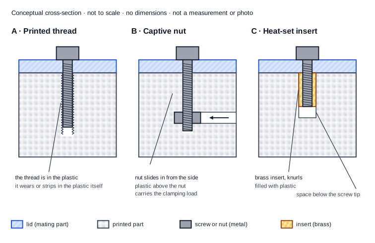
An illustrative cross-section of the three connections shows where the thread sits in each case.
What does the connection need to do?
Start from what the joint has to do rather than from a method. Throughout this article we use one invented example: a small enclosure for an electronics board, with a removable lid and four small screws. It is not a customer project and has not been tested; it is a low-risk example for explaining the choices.
For that enclosure, ask:
- What is being joined? A thin printed lid that has to sit flat on the rim.
- How often does it open? A few times a year for maintenance, or every day? A joint opened twice asks less than one opened a hundred times.
- Which side can you reach? Only from the top, or also from below or the side? A nut usually needs access from a second side; an insert does not.
- How much room is there? A screw boss, the small tube of plastic around the screw hole, needs wall. Not every method fits in a tight corner.
- What tools are available at assembly? A screwdriver is everywhere. Installing an insert needs a hot tool and a stable set-up.
- May the fastener be visible? A nut on the outside looks different from a countersunk screw head.
- Load and environment. Is the lid just held shut, or does something hang from it? Does the enclosure sit in the sun or next to something warm?
- Must damaged hardware be replaceable? You can replace a nut; you cannot replace a thread in the plastic.
- One part or a batch? In a batch, every extra assembly step counts for every part.
Keep two things apart. A metal thread can often be opened and closed many times without wearing itself. That does not make the whole printed joint suitable: the boss can crack, the insert can spin or the lid can deform. The metal thread is one link in the connection.
A short requirements template you can fill in:
Part and mating part: ... Times opened: ... Access: top only / also below or side. Room around the screw: ... Existing screw, nut or insert: ... Load and environment: ... Visible fastener: yes/no. Replaceable: yes/no. Quantity: ...
When should you print the thread itself?
With a printed thread, the thread is part of the model's shape and the printer builds it in layers. That is different from driving a screw into a plain hole, where the screw forms the thread in the plastic. There are several situations:
- A printed internal thread for a metal screw. The screw engages a plastic thread that was already in the file.
- Two printed parts with mating threads, such as a container and its cap.
- A larger custom closure, for example a cap on a jar, with a thread you design yourself.
- A screw in a hole without a thread. A screw driven into a slightly undersized hole forms or cuts its own thread; these are thread-forming or thread-cutting screws. Tapping, cutting a thread into a printed hole with a tap, belongs to this group too. None of this is a printed thread, even though the thread ends up in the plastic.
Why small metric threads are difficult
A standard M3 thread has a pitch of 0.5 mm: the distance from one thread crest to the next. A common 0.4 mm nozzle lays down a line of roughly that width; Prusa, for example, gives a perimeter width of 0.45 mm on a 0.4 mm nozzle in its profiles. The printer then cannot follow the fine V-profile of such a thread accurately. Larger, coarser threads suffer much less from this. There is no fixed smallest size that always works; it depends on nozzle, material, profile and orientation.
For a printed thread, check:
- Diameter and pitch. The larger and coarser the thread, the better its shape prints.
- The real geometry. In many CAD programs a thread is a cosmetic representation by default: the drawing shows a thread, but the exported model contains a plain hole or cylinder. Autodesk documents that in Fusion you tick the Modeled option in the thread command to get a physical thread instead of a cosmetic visual representation. So check the exported file and the slicer preview.
- Clearance between the parts. Autodesk also notes that printed threads are often too tight because of the accuracy of the printing process, and suggests, among other fixes, moving the thread faces of one part. How much clearance you need depends on your printer and material. How to agree clearance is covered in tolerances and clearance for 3D printing.
- Orientation. With the thread axis vertical, the thread is built round, layer by layer. With the axis horizontal, the profile forms differently at the top and bottom. The trade-offs are in choosing a 3D print orientation.
- Cleaning and inspection. An internal thread with strings or support in it turns stiffly. Can you reach it to check it?
- Use and wear. How does it feel when you screw it in, and is that still the same after a number of cycles? That has to be investigated; it does not follow from the drawing.
Next step: inspect the exported model and the slicer preview, then print a short test piece with only the thread and its mating part before you print the whole part. A successful large cap tells you nothing about a small M3 thread in the same material.
When is a captive nut the practical choice?
With a captive nut you print a pocket shaped like the nut. The nut sits in it and the screw comes in from the other side. The thread is then metal, and a damaged nut can often be replaced. There are three common variants:
- A hexagonal pocket that stays accessible, for example on the inside of the enclosure. You press the nut in at assembly.
- A side-entry pocket. The nut slides in sideways and is then enclosed.
- A nut embedded during a paused print. The printer pauses, you place the nut and the printer prints over it. Prusa documents that such a pause is inserted before the layer you select, and warns that inserted items need to be firmly in their slots or they will get stuck to the print head as it passes. Choose, in the preview, the layer at which the pocket is still open, and check that the nut does not stick up above that layer. The steps differ per printer and slicer; follow your own printer's documentation for them.
What to watch:
- Your nut's actual size. Look up the width across flats and the thickness in the standard or the supplier's drawing, and measure a few of your own nuts.
- Fit. Too tight and the nut will not go in or the wall splits; too loose and it drops out during assembly. Printed holes often come out slightly different from the drawing.
- Anti-rotation. The hexagon has to stop the nut turning when you tighten or loosen the screw. A round or oversized pocket does not.
- Material behind the nut. When the screw pulls on the nut, the nut presses against the plastic between it and the lid. If that layer is thin, the nut can pull through.
- Alignment. The screw hole and the nut must line up, or the screw starts crooked.
- Does the nut stay put when the screw is out? With a side slot or an open hexagon the nut can fall out during disassembly.
- Replacement. If the pocket or nut is damaged, can you still do anything, or is the part finished?
A 2020 test by CNC Kitchen, with M3 screws in PETG and three specimens per variant, showed how much pocket direction matters. The nut seated from below held clearly more force in pull-out than the nut in a side-entry slot. In tightening, both nut variants failed when the PETG under the nut gave way and the nut started to turn. Those are results for those specimens, not values for your part. The pattern is useful, though: what holds the nut back determines the joint.
So drawing a hexagon does not guarantee a good joint. Fit, support and access decide it together.
Can you reach both sides, and may the nut be visible? Then compare first with a simple through-bolt and a loose nut. No pocket, no thread in the plastic, and everything stays replaceable.
Do not press an ordinary nut into the plastic with a soldering iron as a substitute for an insert. A nut has no knurls or ribs designed to anchor in plastic, and you do not know what state the surrounding material is in afterwards.
When is a heat-set insert worth using?
A heat-set insert is a bush with an internal thread, usually brass, with knurls or ribs on the outside. A heated tip carries heat through the insert into the plastic. The plastic melts locally, flows into the knurls and solidifies again. SPIROL, an insert manufacturer, writes that the plastic must entirely fill the insert's external features for the best performance, and that as much as 75% of an insert's performance comes from how well it was installed. From pull-out tests filmed with a high-speed camera, CNC Kitchen concludes that the plastic does not bond to the brass but locks mechanically into the knurling.
What does an insert give you?
- A metal thread in a single hole, assembled from one side. That helps the example lid, where you cannot reach the underside of the bosses.
- Less wear on the thread itself. The screw runs in brass, not in plastic.
- Anchoring against rotation. In CNC Kitchen's 2020 PETG test, the insert took about three times as much tightening torque as a screw driven straight into a slightly undersized hole, until the insert itself started to turn in the plastic. In pull-out, the two were roughly equal in the same specimens. So an insert does not make the joint stronger in every respect; its advantage is mainly resistance to turning and repeated use. Do not treat these results as a tightening torque or load for your part.
The insert does not make the surrounding plastic stronger. The boss still has to hold the insert, the lid still has to seat properly, and a wall that is too thin can bulge during installation or crack later. Assess the boss separately; loading and the material around holes are covered in how strong are 3D-printed parts?.
Not every insert behaves the same way. Heat-set inserts, press-in inserts and inserts moulded in during injection moulding have different shapes and need different holes. Use the hole size and method for the insert you actually buy. SPIROL also distinguishes straight and tapered inserts, each with its own hole shape.
An insert is therefore not automatically more professional than a nut; it is a different trade-off between installation work, space and access.
Investigate an insert when: the joint opens often, you can reach the hole from one side only, a nut cannot be placed or keeps falling out, or a screw in the plastic already strips during light assembly.
Something simpler may do when: the joint opens only a few times, both sides are reachable for a bolt and nut, there is too little wall around the hole for an insert, or nobody can install the inserts reliably.
How do you install and inspect an insert?
This is a sequence of work, not a temperature recipe. The right setting depends on the insert, the tool and the material; follow the insert maker's instructions.
- Check that material and insert suit each other. Heat-setting works with thermoplastics, which soften again when heated. SPIROL describes heat and ultrasonic installation for thermoplastics only, not for thermosets.
- Check the hole before installing. Measure the diameter, check the depth and make sure there are no strings or support in it.
- Hold the part firmly. It should sit square and stable, with support under the boss, so you do not push the whole part down.
- Use temperature-controlled equipment with a suitable tip. A soldering iron with an insert tip, or an insert press. Do not simply copy your printing temperature, and do not use more heat or force than needed.
- Keep the insert square and control the depth. An insert press helps in a batch. Do not push beyond the surface: SPIROL, for moulded parts, calls for an insert flush with the surface and protruding no more than 0.13 mm.
- Let it cool before loading or tightening. CNC Kitchen notes that inserts tend to creep back out straight after melting; hold it in place until the plastic has solidified.
- Inspect the result. Is the insert square? Is there melted plastic in the thread? Is the wall around it bulging or cracked? Does the lid still sit flat?
- Fit the real screw with the real lid. Do not tighten until something gives; check that the screw engages smoothly and the lid clamps.
The tip and the insert are hot enough to burn you. Keep the tool in a stand, do not hold the part in your hand while installing and work in a ventilated space.
Which dimensions must you design around?
M3 is the size of the screw thread, not the size of every hole in the joint. Around one M3 screw you quickly have four or five different holes:
- The nominal thread, for example M3: screw diameter and pitch.
- The clearance hole in the lid. Larger than the screw, so it passes through freely.
- A pilot hole for a screw that engages the plastic directly. Smaller than the screw, so there is material to form a thread in.
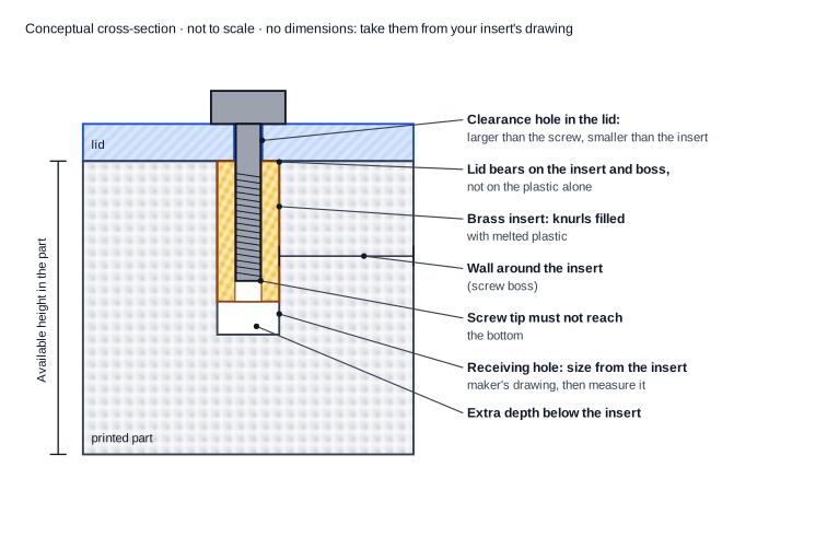
- The receiving hole for an insert. Larger than the screw, with a size that belongs to the insert.
- The nut pocket. A hexagon with room to insert the nut.
- A printed internal thread. A thread shape with clearance.
So never carry one M3 size across all of those holes.
For an insert
Record:
- which insert model you use, with its part number;
- that insert's outside diameter and length;
- the recommended hole size and shape from the maker;
- where the insert sits and how much depth is available;
- how much plastic remains around the insert;
- how far the screw engages the insert;
- what the lid bears on;
- the screw length, and whether it can reach the bottom of the hole;
- whether there is room for the installation tool.
An illustrative anatomy of an insert joint shows these points in one cross-section.
A worked example with one specific insert
This example applies only to the CNC Kitchen heat-set insert M3 × 5.7 (part TC-M3x5.7), using the dimension table on the maker's product page as it stood on 24 September 2026. Other inserts with the same M3 thread can have different dimensions.
- Length: 5.7 mm. Outside diameter: 4.6 mm. Recommended hole diameter: 4.0 mm. Minimum wall thickness: 1.6 mm.
- Blind-hole depth: at least the length plus 1 mm according to the table, so 6.7 mm. SPIROL, for its own inserts, calls for at least the length plus two thread pitches. With the 0.5 mm M3 pitch, that is also 1 mm extra.
- Clearance hole in the lid: SPIROL writes that this hole must be larger than the screw but smaller than the face of the insert. Otherwise the lid does not bear on the insert, and the screw pulls the insert up out of its hole. For this example, larger than 3 mm and smaller than 4.6 mm.
- Screw length: say the lid is 3 mm thick. An 8 mm screw then reaches 5 mm below the lid: inside the insert and 1.7 mm above the bottom of the hole. A 10 mm screw reaches 7 mm and bottoms out in a 6.7 mm hole before the lid is tight.
You will see two kinds of wall advice. CNC Kitchen's table gives a minimum for printed parts. SPIROL, for moulded plastic, gives an optimum boss diameter of two to three times the insert diameter, here roughly 9 to 14 mm. They answer different questions: what is minimally needed, and what performs best in a moulded part. Neither tells you what your printed boss can take.
Design dimension and printed dimension are not the same
A maker's recommended hole size is the size the finished hole should have, not automatically the size you draw in CAD. In CNC Kitchen's 2026 PLA test, printed holes came out about 0.25 mm smaller than designed. The author keeps 4.0 mm as the correct hole size, therefore draws small holes 0.2 to 0.3 mm larger in CAD, and warns that results vary by printer and material, and by hole direction: horizontal, vertical and angled holes turn out differently. Even the insert seller does not offer a universal CAD size. So print a test hole, measure it and then adjust your model. Keeping design size, variation and clearance apart is covered in tolerances and clearance for 3D printing. If you need to change a hole in an STL without the CAD file, see editing an STL without the CAD source.
For a nut pocket
Record: your nut's actual width across flats and thickness, the extra room needed to insert it, the pocket depth, how the hexagon prevents rotation, how much material sits behind the nut, and which side the nut goes in from.
Why does the connection strip or the insert come loose?
Look first at what actually happens, because each kind of failure calls for something different. With a stripped thread, the thread in the plastic has sheared off. With rotation, the nut or insert spins. With pull-out, it comes loose along the screw axis. Sometimes the printed part around it fails: the boss cracks or bulges. Sometimes it is the screw or the assembly: wrong length, started crooked or overtightened. And sometimes the joint changes over time: plastic that slowly deforms under sustained load is said to creep. Research on printed PLA shows specimens under constant tensile load continuing to stretch, which can reduce clamping force.
| What you observe | What to inspect | Possible mechanisms | A useful next check |
|---|---|---|---|
| The screw keeps turning in the plastic | Hole size, how deep the screw engages, how often the joint has been opened | Plastic thread sheared, pilot hole too large, too many cycles | A test piece with a nut or insert, or a smaller pilot hole |
| The nut spins in its pocket | Fit of the hexagon and the wall around it | Pocket too loose, or plastic giving way under the nut | A tighter hexagon or more wall; see whether the pocket corners are crushed |
| The insert rotates in the plastic | Is the plastic filled in around the knurls? | Hole too large, installed too cold or too much torque | A cross-section or a second specimen with a measured hole |
| The insert pulls out | Depth, hole size and how the lid seats | Hole too loose, lid pulling the insert up, screw bottoming out | Re-measure the lid clearance hole and screw length |
| The boss cracks | Wall thickness, direction of the crack relative to the layers | Wall too thin, wall bulged during installation, crack along a layer | More wall or a different orientation; see the strength guide |
| The screw becomes hard to turn | Plastic in the thread, tilted insert, alignment | Melted plastic in the insert, insert installed crooked, misaligned holes | Check the insert and alignment before turning harder |
| The screw bottoms out before the lid is clamped | Screw length against hole depth | Screw reaching the bottom | A shorter screw or a deeper hole |
| The lid is looser after a while | Heat, load and material | Creep or relaxation of the plastic, a screw backing out | Re-check after a fixed period under the same conditions |
You cannot read a definite cause from appearance alone; the table gives directions to investigate. More infill is not the default answer either: the thread or insert usually sits in the walls around the hole, not in the infill. For loading, walls and orientation in general, read how strong are 3D-printed parts?, and for material behaviour with heat, the overview at choosing a 3D printing material.
Which method fits your situation?
Three short situations show how the trade-off works out. They are examples, not fixed rules.
1. A small enclosure that has to open repeatedly. The example lid with four screws, opened regularly for maintenance. Investigate a heat-set insert and a captive nut. Access decides it: if you can place a nut in a pocket on the inside and it stays there, that is simple and cheap; if you can only reach the boss from the top, the insert wins. A screw straight into the plastic wears with every opening. Before deciding you need: the room around the bosses, the screw you want to use and a test piece of one boss with its lid.
2. A low-risk prototype assembled only occasionally. A screw in a pilot hole, or a through-bolt with a nut, is often enough here. The trade-off is speed against reusability: installing inserts takes time that a trial does not always repay. You need: an idea of how often the prototype will be opened again, and whether the final design will move to a different connection.
3. A large screw cap or closure turned by hand. Here a printed thread can fit well, because the thread can be large and coarse and no metal part is needed. The trade-off lies in clearance, orientation and thread profile. You need: a short test piece with only the thread and the cap, printed in the same orientation and material as the final part.
When choosing, also look at the work around the joint, not only at the price of a nut or insert: the assembly step per part, handling loose hardware, whether the joint can be repaired and whether the tools can reach.
How do you evaluate a prototype connection?
Judge a trial joint by what it has to do. A connection has only been assessed once it has been used the way it is meant to be used. Decide in advance what counts as good enough, for example: after opening and closing ten times, the lid still sits flat, with no visible cracks and no insert turning.
- The screw starts square and turns in smoothly.
- No force is needed to bring the parts together.
- The lid sits flat and closes as intended.
- You can assemble and disassemble the way you will in use, with the real tools.
- There is no visible damage or permanent deformation after assembly.
- The nut or insert does not turn or move.
- The screw is long enough to engage properly and does not reach the bottom.
- The result is recorded against the criterion you chose beforehand.
Keep the kinds of test apart. Checking that you can assemble the part in practice is different from assessing how the joint behaves after repeated opening. Measuring pull-out or resistance to rotation are separate, destructive tests. None of them tells you by itself whether the part suits its real load. One successful assembly says nothing about how long the joint will last, and the force at which a specimen fails is not an allowable load. How to tie a trial print to a revision and fixed checkpoints is covered in assessing a 3D-printed prototype. Where a failure could cause harm, the application needs its own engineering assessment and validation.
What should you provide when ordering a part?
You do not have to design the connection yourself to make a good request. Describe the result and the conditions. Send, where you have them:
- the file, or photographs with dimensions;
- the mating part, such as the lid or whatever it fastens to;
- the screw, nut or insert you already use or want to use, with size and length;
- where you can reach during assembly;
- how often the joint has to open;
- how much room there is;
- the environment and loading;
- whether assembly is part of the job;
- whether the fasteners must be replaceable.
An example of a useful description:
An enclosure for a small circuit board, with a lid that opens about four times a year for a battery change. I use M3 screws, 8 mm long. I cannot reach the underside of the screw bosses. The enclosure is used indoors. Please deliver it with the fastening already installed.
A lot follows from that already: assembly from one side points towards an insert, the screw length sets the depth, and you are asking for assembly. Whether assembly is included is agreed per quote; see 3D printing and assembly. If the model first needs changing for the connection, 3D modelling is the better starting point.
Want a part with a screw connection made? Send your file or photographs and the answers above via 3D-printed parts. We look at which connection fits before anything is printed.
Frequently asked questions. The answers below add to the explanation above.
Can I keep the same hole if I switch insert supplier?
Not without checking. Inserts with the same thread can have a different outside diameter, length, knurl pattern and recommended hole size. Look up the new insert's drawing and make a new test hole.
Can a damaged threaded connection be repaired?
Sometimes. A damaged nut can be replaced; a worn hole in the plastic can sometimes be enlarged for an insert if enough wall remains. A cracked boss is usually a reason to reprint the part with a changed design.
Does a heat-set insert work in a resin print?
Not in the same way. Heat-setting works because thermoplastic softens again; most cured resins do not. CNC Kitchen mentions gluing, rather than melting, for resin prints. For the differences between the processes, see comparing FDM, SLA and SLS.
What this article is based on
This article combines design guidance from insert manufacturer SPIROL, which mainly concerns moulded plastic, with two documented tests and installation tips from CNC Kitchen, which sells inserts itself. It also uses the dimension table of one specific insert, software documentation from Autodesk and Prusa, and a study on creep in printed PLA. The tests apply to their own specimens, material and printer, not as a general rating. OmniTechs has not carried out its own comparative test of threaded connections for this article. The enclosure is an invented example, and the screw lengths in the worked example are arithmetic, not measurements.