
A smaller layer height can make some surfaces look smoother, but it does not improve every kind of detail. Before you choose 0.12 mm over 0.20 mm, work out which surface or feature you are actually trying to improve. If it is a gently sloped or curved face, finer layers may help. If it is tiny lettering, a rough top surface, a visible seam, support marks, a round part that looks faceted or a part that does not fit, the fix usually lies somewhere else.
This guide covers ordinary FDM/FFF printing, where a printer lays down molten filament in lines and layers. The values 0.12, 0.20 and 0.28 mm are examples for a common 0.4 mm nozzle. They are not quality grades or an industry standard, just three sensible places to start a comparison.
As a first orientation:
- 0.12 mm is worth investigating when a visible face slopes gently or curves, such as a dome, an angled front or a rounded edge, and that face matters.
- 0.20 mm is a practical baseline for many parts on a 0.4 mm nozzle: enclosures, holders, prototypes and parts made mostly of vertical walls and flat tops.
- 0.28 mm may be enough for large, simple or hidden parts where print time matters more than fine layer lines, provided your profile and material handle that height well.
Already looking at a specific defect? Jump to When will a smaller layer height not be enough? and then read the explanation behind it.
What does layer height actually change?
Layer height, sometimes called layer thickness, is the height of one printed layer in the Z direction, the direction in which the printer builds the part. Bambu Lab describes it as the vertical resolution of the model. A smaller layer height means more layers for the same part height, so the shape is sampled more finely from bottom to top.
A simple worked example
Take a part 20 mm tall. At 0.28 mm it needs roughly 72 layers, at 0.20 mm 100 layers and at 0.12 mm roughly 167 layers. The first layer often has its own height, so your slicer will show slightly different counts. Every layer is another pass of the print head, with its own walls, layer change and, usually, seam point.
The same grid also decides how heights are represented. Raised text 0.5 mm tall can only be built from about two layers at 0.28 mm, so its height is rounded. At 0.12 mm the height follows the design more closely. That is about height in Z, not about how crisp the letters are in the horizontal plane.
Stair-stepping on sloped and curved faces
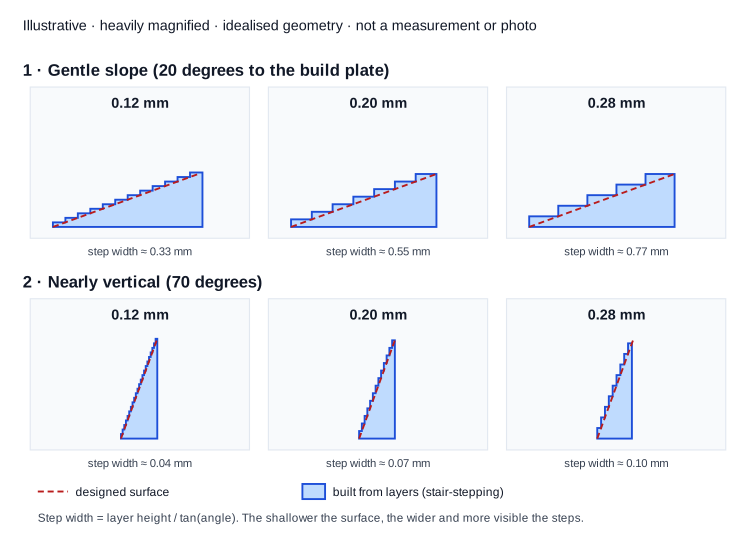
A sloped or curved surface is built as a staircase of flat layers. This is called stair-stepping. Each step is one layer height tall. How wide each step is depends on the angle of the surface relative to the build plate. In an idealised geometric sketch, the step width equals the layer height divided by the tangent of that angle.
| Surface angle relative to the plate | Step width at 0.12 mm | At 0.20 mm | At 0.28 mm |
|---|---|---|---|
| 20 degrees, a gentle slope | about 0.33 mm | about 0.55 mm | about 0.77 mm |
| 70 degrees, nearly vertical | about 0.04 mm | about 0.07 mm | about 0.10 mm |
These are calculated from geometry, not measured on prints. They still show the key pattern: on gentle slopes and at the top of a dome the steps become wide and visible, while on nearly vertical walls they are barely there. The illustrative stair-stepping diagram shows the same slope at all three heights.
What layer height is not
- Not the nozzle diameter. The nozzle mainly sets roughly how wide an extruded line is. Prusa gives a perimeter width of 0.45 mm on a 0.4 mm nozzle as an example.
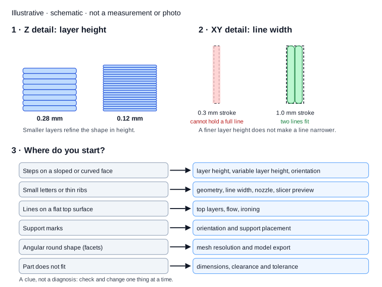
- Not extrusion width or XY detail. How narrow a wall, letter or groove can be in the horizontal plane depends mostly on line width, toolpath and geometry. A smaller layer height does not make a line narrower.
- Not dimensional accuracy. Layer height changes the layer pattern and vertical detail, but it does not set how far a hole or outside dimension may deviate. That is a separate subject: 3D-printing tolerances and clearance.
- Not overall print quality. Seams, top surfaces, support marks, stringing, warping and mesh quality each have their own causes.
Layer height also has limits. Bambu Lab gives 20 to 70 percent of the nozzle diameter as a reasonable range, so 0.08 to 0.28 mm on a 0.4 mm nozzle. Prusa uses 80 percent as the upper limit. All three example values fall inside both ranges, though 0.28 mm sits at the top of Bambu Lab's range.
0.12, 0.20 or 0.28 mm: where do you start?
There is no winner. The right first choice depends on which face is visible, how it runs, how much appearance matters and how much extra print time that is worth. Use the table to decide which comparison to make first.
| Layer height | Situation worth investigating | Feature to inspect | Main trade-off | When another setting may matter more |
|---|---|---|---|---|
| 0.12 mm | A visible finished product with gentle slopes, domes, rounded edges or a round opening printed horizontally | Steps on the sloped or curved visible face, viewed under raking light | More layers and, in most cases, a longer print | Small lettering in the horizontal plane, a rough top surface, a seam, support marks or a faceted model |
| 0.20 mm | A prototype, enclosure, holder or functional part with mostly vertical walls and flat tops | Whether the visible face looks good enough for its purpose with this layer pattern | A balance between layer lines and time in many profiles; not a standard | If one visible face slopes gently, variable layer height can target it more precisely |
| 0.28 mm | A large, simple or hidden part, or a quick shape check | Whether coarser layer lines and steps get in the way of use or assessment | Shorter printing against more visible layers and coarser rounding in Z | Fine raised features in Z, visible slopes, or a profile that does not handle this height well |
A few questions help you choose:
- Where is the demanding surface? Does it cover the whole part, or only a small dome on top? In the second case, printing the entire part finer is often an expensive answer to a local problem.
- Is this a test or the finished item? A shape test can be coarser. A product that sits on a desk or a shop shelf is judged on its visible face.
- How long may it take? Compare the print time for each option in the slicer. How much longer finer layers take varies from model to model.
- How will it be seen? Up close under angled light you see far more than from a metre away.
Where will you notice the difference most?
Three examples show why the same setting changes one surface a lot and another hardly at all.
A curved or sloped surface
A dome, an angled front or a rounded edge is the classic place where layer height shows. The gentler the slope, the wider the steps and the clearer the lines under angled light. This is where 0.12 mm can make a real difference. Look at print orientation too. A face that slopes gently when the part lies flat may be almost vertical when you tilt the part, which shrinks the steps without touching the layer height. Tilting also moves support, seams and the direction of the layers. That trade-off is covered in choosing 3D-print orientation around visible faces, fit and loading.
Small text or a logo
Say a name has to sit on the front, with letters a few millimetres tall and strokes under half a millimetre wide. If the part lies flat, those letters are drawn in the horizontal plane, as XY detail. A 0.4 mm nozzle lays lines roughly 0.4 to 0.45 mm wide. A stroke narrower than one line cannot be filled properly by the slicer. It may disappear, merge with its neighbour or come out thicker. A smaller layer height does nothing about that.
What to investigate instead:
- Geometry: are the letters wide enough for the line width, and raised or recessed enough?
- Toolpath: does the slicer preview show each letter as a continuous path?
- Orientation: if the text sits on a vertical wall, letter heights are built in Z and layer height does matter.
- Nozzle: a smaller nozzle allows narrower lines. Bambu Lab recommends a 0.2 mm nozzle for models with a lot of detail. It is more prone to clogging, prints more slowly and often gives weaker parts.
For names and logos on small objects, the design side is covered in designing a custom keychain that stays readable. The Z-detail versus XY-detail diagram shows the difference.
A functional enclosure
An electronics enclosure usually has surfaces with different priorities:
- Visible face: the front with a rounded edge or a logo. Layer appearance may matter here.
- Hidden face: the back against a wall, or the inside. Coarser is fine.
- Top surface: a flat lid. Its quality depends mainly on the top layers rather than on steps, because a horizontal face has no stair-stepping.
- Fit-critical areas: a snap fit, screw hole or lid that has to close. Here the question is dimensions and clearance, not layer lines.
Because one part contains all of these zones, the question is not which layer height is best but which zone should drive the choice. If the rounded front comes first, compare 0.12 and 0.20 mm, or use variable layer height on just that edge. If the lid comes first, look at top layers and ironing before anything else.
When will a smaller layer height not be enough?
Many visible defects look like layer lines but come from somewhere else. Treat the table as a starting point for investigation, not as a diagnosis. What you see is a clue, not a confirmed cause. Change one thing at a time and compare under the same viewing conditions.
| What you see | What may be causing it | What to check | Why finer layers will not simply fix it |
|---|---|---|---|
| Lines or ridges on a flat top surface | The top-layer pattern, too few top layers, flow, or a top skin sitting over infill | Number and thickness of top layers, top pattern, flow, and whether ironing suits the part | A horizontal face has no stair-stepping; at a lower layer height you often need more top layers for the same thickness |
| A vertical stripe or row of small bumps on a side | The seam: every closed wall loop starts and ends somewhere | Seam position in the slicer and which side is visible | More layers mean as many or more seam points; the seam does not go away |
| Rough patches where support touched | Support contact surfaces | Orientation, support placement and whether that contact face may be visible | Support marks depend on where support touches, not on layer height |
| A round part looks angular, with small flat facets | The model itself is made of triangles that are too coarse | The STL file and its export settings | The printer follows the facets in the file; finer layers only reproduce them more faithfully |
| Small text vanishes in the slicer preview | Letter strokes narrower than the line width | Layer-by-layer preview, line width, letter size and depth | The problem is in XY; layer height does not change line width |
| The part does not fit | Dimensional deviation, shrinkage, clearance or a wrong design dimension | Measure against the design dimension and the agreed clearance | Layer height is not a tolerance setting |
For round parts that look faceted, start with the export: exporting STEP to STL without unnecessary facets. For fit problems, start with dimensions and clearance, not with the layer pattern.
Finer layers, ironing or post-processing?
These three routes solve different things.
- Finer layers make steps smaller on sloped and curved faces. They do little for a flat top surface and do not remove layer lines.
- Ironing runs the hot nozzle over the last top layer again with very little material. Prusa and Bambu Lab both describe it for flat top surfaces. Bambu Lab states plainly that ironing will not smooth out the lines between layers on a curved top surface. It adds print time, and flow, spacing and speed need to suit the material and nozzle.
- Post-processing, such as sanding, filler, primer or paint, is a separate route when a surface must end up smoother than FDM can deliver on its own. It takes manual work and can change the dimensions of a face.
A fine layer height can reduce how much post-processing you need, but it does not replace it. Which finish suits which face is covered in choosing the finish before producing a 3D print.
Finer layers, a smaller nozzle or a different orientation?
"I want more detail, so I need smaller layers" is the most common line of thinking. More detail can mean four different things, and each needs a different fix.
| What "more detail" really means | Direction | What helps | How to recognise it |
|---|---|---|---|
| Smaller steps on a sloped or curved face | Z | A smaller layer height, variable layer height or a different orientation | The problem sits on sloped or curved faces and is less visible on vertical walls |
| Sharper small letters, thin ribs or narrow grooves | XY | Adjusting the geometry, checking line width, orientation or a smaller nozzle | The slicer preview shows missing, merged or thickened features, even at a fine layer height |
| A face that should be smoother or sit at a different angle | Orientation | Tilting the part so the visible face stands steeper or support touches elsewhere | The visible face lies at a shallow angle or needs support in its current position |
| A rounder shape without small flat facets | Source geometry | Re-exporting the model with a finer mesh | The facets are already visible in the 3D view of the file, before slicing |
To work out which one you need:
- Look at the file itself first. If you can see facets in the 3D view, it is a mesh problem.
- Then slice and step through the preview layer by layer. If letters or ribs are missing on the layer where they belong, it is XY.
- Picture the part rotated. If the visible face would be nearly vertical in another position, orientation is a candidate. Check what happens to support, seams and the direction of any load. If the part also has to carry something, weigh that with how strong are 3D-printed parts?.
- If only stair-stepping on a slope remains, layer height is the right lever.
What does a smaller layer height do to print time and cost?
More layers usually means more print time, but there is no fixed formula. Halving the layer height does not automatically double the print time. The difference depends on the model and the profile: speeds, minimum layer time for cooling, travel moves, the number of walls and top layers, support and how much small detail there is. Bambu Lab's documentation shows one example model that took 1 hour 19 minutes at 0.08 mm and about 28 minutes at 0.28 mm. That applies to that one model, not as a conversion factor for yours.
When thinking about cost, keep these apart:
- Slicer estimate: an estimate per option, useful for comparison.
- Actual machine time: can differ because of heating, calibration and printer settings.
- Material: the volume of the model does not change with layer height, so do not expect finer layers to use proportionally more filament. The slicer shows small differences caused by walls, top layers and support.
- Labour and finishing: finer layers can reduce sanding, while ironing and seam adjustments take tuning time.
- Final price: when you outsource a print, preparation, print time, material, inspection and finishing add up. How that works is explained on what 3D printing costs.
The sound way to make the trade-off:
- Take the same model in the same orientation.
- Keep the rest of the profile the same, or write down what changes with it.
- Slice at 0.20 mm and at 0.12 mm, or at 0.20 and 0.28 mm.
- Compare the estimated time and weight. The Bambu Studio preview shows time and material per line type, so you can see where the extra time comes from.
- Decide whether the visible improvement on the face that matters is worth that time.
Is variable layer height a good middle ground?
Often, yes, when the demanding surface is only part of the object. With variable or adaptive layer height, the slicer prints thin layers only where the model slopes or curves, and thicker layers elsewhere. Bambu Lab uses models with a rounded top or a slope as its typical example: only the local layer height drops, while the rest keeps the original height. Prusa writes that this can give significantly shorter print times with little loss of quality. How much time you save depends on the geometry and settings.
What to check in the slicer:
- The layer-height colour view in the preview: does the fine zone sit exactly on the visible sloped or curved face?
- The transitions: are they gradual, so no visible band appears?
- Limitations: in Bambu Studio, a prime tower requires the same variable layer height on every object on the plate, and the feature is not supported with organic tree supports.
Variable layer height only changes the Z direction. It will not make small letters in the horizontal plane any sharper.
What does a real workshop example show?
Our page on how we approach 3D printing includes a real workshop case with three print versions. The part is a long, U-shaped piece of a folding stand in black PLA+, printed with a 0.4 mm nozzle, with a horizontal hole near the rounded end. The customer supplied the model, and the case is anonymised.
What happened in each version:
- Version 1, standard settings. Filament sagged at the top of the horizontal hole, because the upper arcs of the circle had to bridge without support. The outer edges were ragged.
- Version 2, 0.12 mm layers. In the photo the hole looks rounder. According to the case record, several settings changed at the same time; after version 1, bridge and overhang speeds, cooling and bed adhesion were also worked on. New issues appeared: slight corner lift and a horizontal line at the height of the hole. The top surface still showed clear diagonal toolpaths.
- Version 3, tuned ironing and a relocated seam. The top surface became more even and the seam moved to the less visible underside and inner face. Fine FDM lines and a local seam mark remained visible.
What you can and cannot take from it:
- You can: see that a horizontal hole is a curved surface built up in Z, exactly the kind of shape where layer height plays a role. It is plausible that 0.12 mm contributed to the rounder look.
- You cannot: tell how much of the improvement came from layer height. Several settings changed at once, so this comparison does not isolate it.
- You can: see that each visible problem needed its own route. The sagging needed bridge and overhang settings, the top surface needed ironing and the seam needed a different seam position. Finer layers alone would not have fixed those three.
- You cannot: read a measured dimension or tolerance from it. The photos are visual comparisons, not dimensional or load tests.
That is how to use a workshop example: as an illustration of diagnosing one step at a time, not as proof that one setting explains everything.
How do you choose the layer height for your own print?
Work through these steps before you start a long print:
- Mark the visible face. Which side will people see, from what distance and under what light?
- Name what you want to improve. Steps, letters, a top surface, a seam, support marks, facets or fit?
- Decide what kind of problem it is. Z detail, XY detail, top surface, source geometry, support or fit. Use the diagnostic table above.
- Check the orientation. Can the visible face stand steeper without making support, seams or loading worse?
- Check the source geometry. Are round shapes already angular in the file?
- Slice two layer heights that suit your nozzle. For example 0.20 and 0.12 mm, or 0.20 mm with variable layer height on the sloped section.
- Compare estimated time and material. Use the preview to see where the time difference comes from.
- Print a representative sample if the uncertainty matters. Take only the demanding section, in the same orientation, and view both versions under the same light.
- Decide in advance what good enough means. For example: no individual steps visible on the rounded front from 50 cm away. How to record criteria like that is covered in assessing a 3D-printed prototype.
What should you tell us when you order a print?
You do not need slicer expertise to write a good request. Describe the result you want and where it will be seen. For example:
The curved front is visible on a desk. Fine layer lines on the underside are acceptable. The small lettering on the front must remain readable.
That tells us far more than "print it at maximum quality". The choices follow from it: the front gets priority, the underside does not, and for the lettering we look at XY detail rather than layer height alone. Also mention whether it is a test or the finished item, whether any parts need to fit together, and whether you want a finish.
Want something printed where appearance matters? Send your file and a short description of the visible face to our 3D printing service. We will look at which surfaces drive the choice and discuss it with you before anything is printed.
Frequently asked questions. The answers below add to the explanation above.
Does a smaller layer height make a part stronger?
Not predictably, in general. Layer height can affect how well layers bond, but the effect depends on material, temperature, line width and the direction of the load. For a loaded part, start from the load, walls, orientation and design. That approach is set out in how strong are 3D-printed parts?.
Is 0.12 mm always better-looking than 0.20 mm?
No. On vertical walls, flat top surfaces and small details in the horizontal plane the difference is often small. On gentle slopes and domes it is larger. Finer layers do not fix a seam, support marks, facets or a dimensional problem either.
Why does my printer use a different first layer height?
The first layer usually has its own setting so it bonds well to the plate. Bambu Lab's default is half the nozzle diameter, so 0.2 mm on a 0.4 mm nozzle. Prusa's own profiles typically use 0.20 mm as well. That is why the layer count in your slicer differs slightly from a simple division.
Can you remove layer lines completely by printing finer?
No. Even with fine layers and ironing, an FDM print still looks layered, as the workshop case shows. If a surface really has to be smooth, post-processing is a separate step. For very small detail, a different process may suit better: compare FDM, SLA and SLS.
What this guide is based on
This guide combines Prusa and Bambu Lab slicer documentation on layer height, variable layer height, ironing, seam position, nozzle choice and the slicer preview with basic geometry for stair-stepping. The step widths in the table are calculated, not measured. The workshop case is a real, anonymised job from our workshop, but not a controlled comparison: several settings changed at once. OmniTechs has not run its own controlled layer-height test for this guide. Manufacturer advice applies to their own profiles and printers, not as a universal rule for every FDM process.